Slow Progress, But Still Progress

Took Friday off of work to hopefully start cutting strips… didn’t get to it until Sunday due to our friendly postal service (who actually are friendly and pretty much the opposite of all the postal jokes… quick, efficient and reliable). They decided our brick mailbox had sunk over the years and was now too low to be regulation height. Hate to admit it but they were right. It weighed over 1000 pounds and in the last decade or so had sunk almost 7 inches into the ground! My wife picked out a wooden one online and I spent two days making it along with learning a new “finishing” technique known as shou-sugi-ban (plenty of youtube videos showing how). Basically taking a torch to wood and then sanding it. Fairly simple process (although time consuming) and pretty amazing results. If (when) kayak number two is built I just might consider finishing it this way.

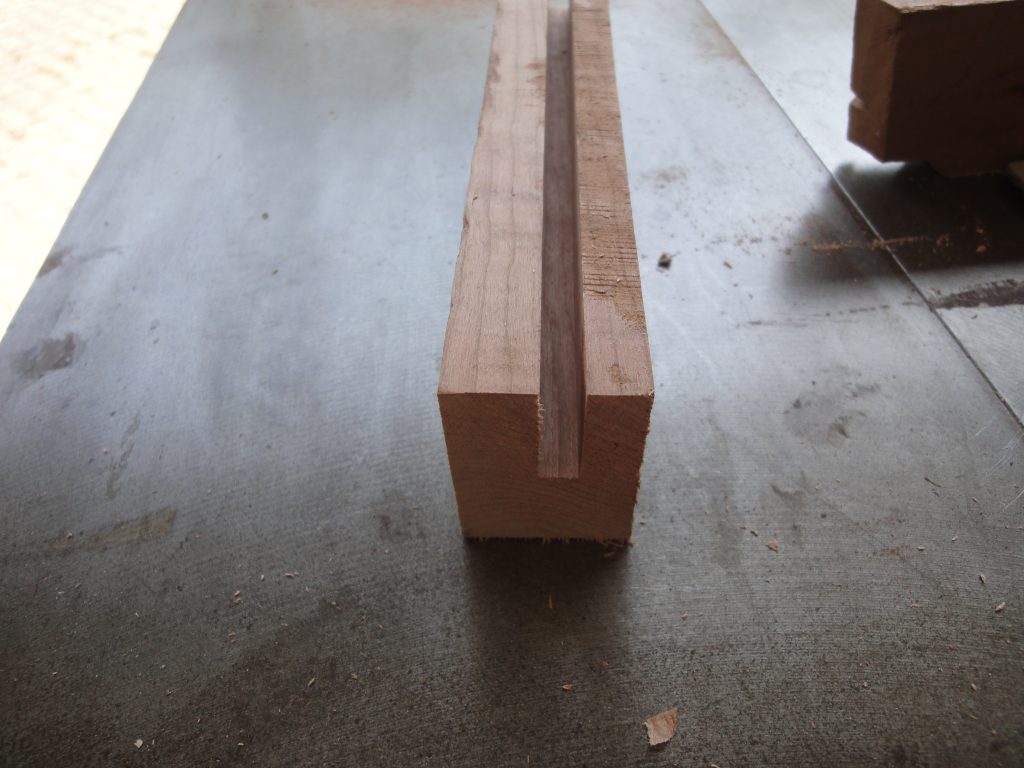
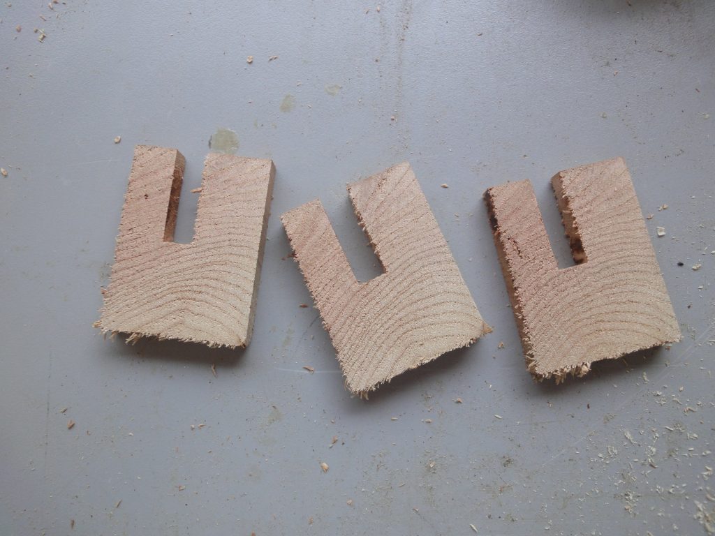
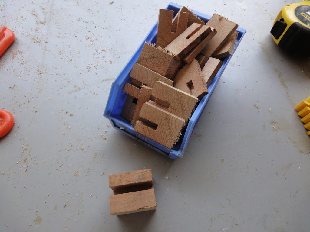
Anyway, I got that done late Saturday afternoon so Sunday was dedicated to kayak work. I started with some utility steps. First I took a piece of hardwood I had laying around, cherry I think, and cut a grove in it just over 1/4″ in width and then sliced it into approximately quarter inch pieces. I won’t go into why now, just that these will come in handy later on.

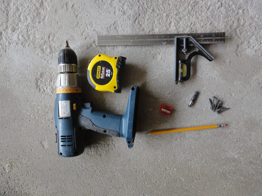
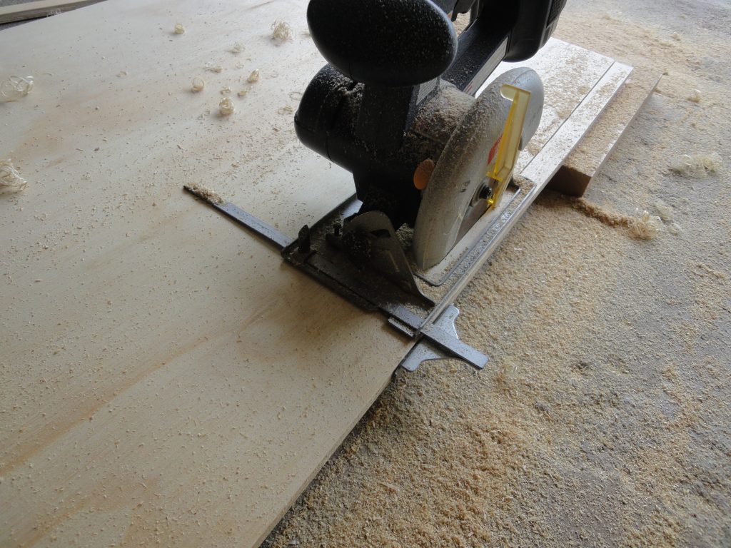
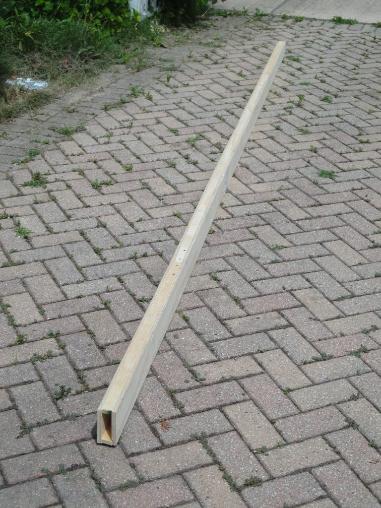
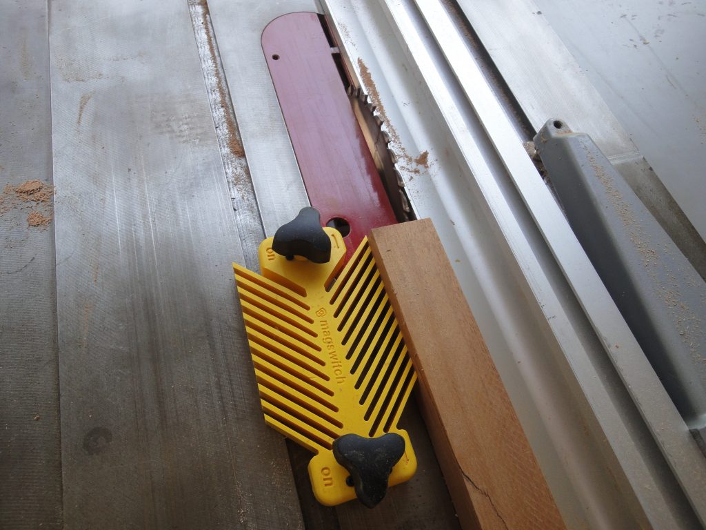
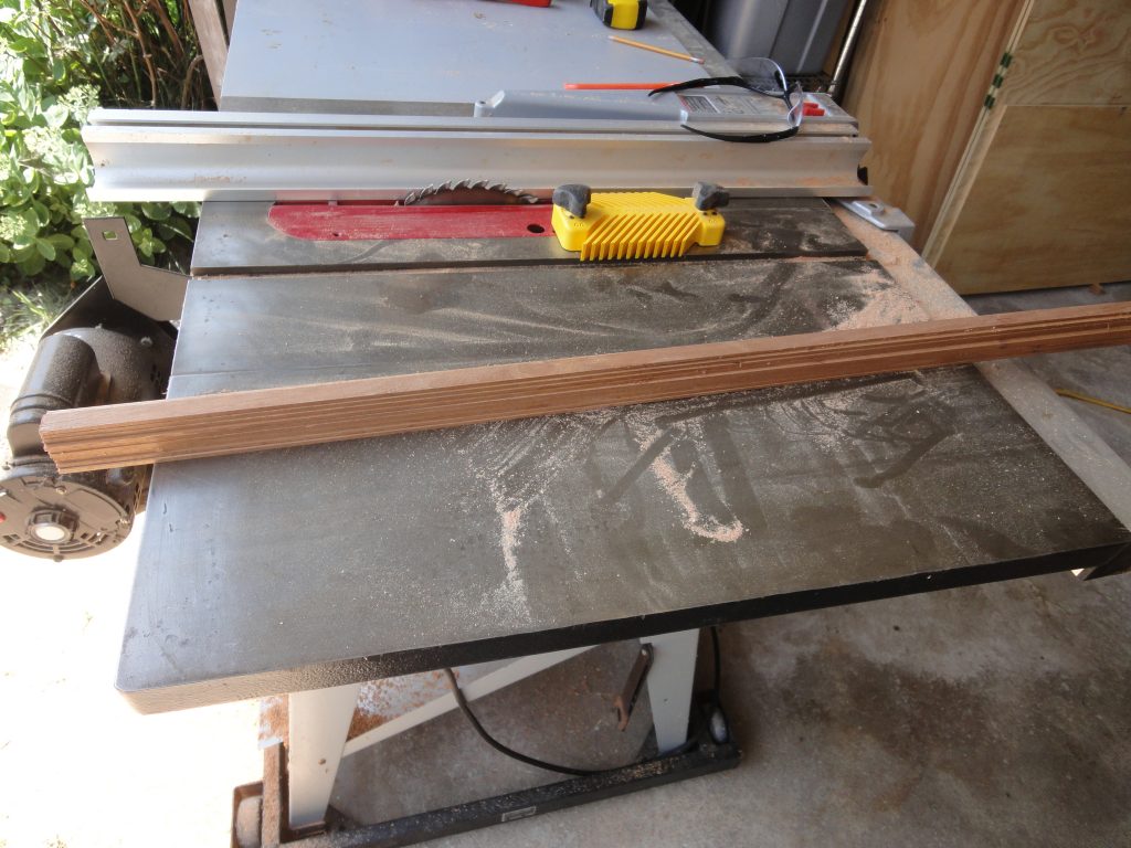
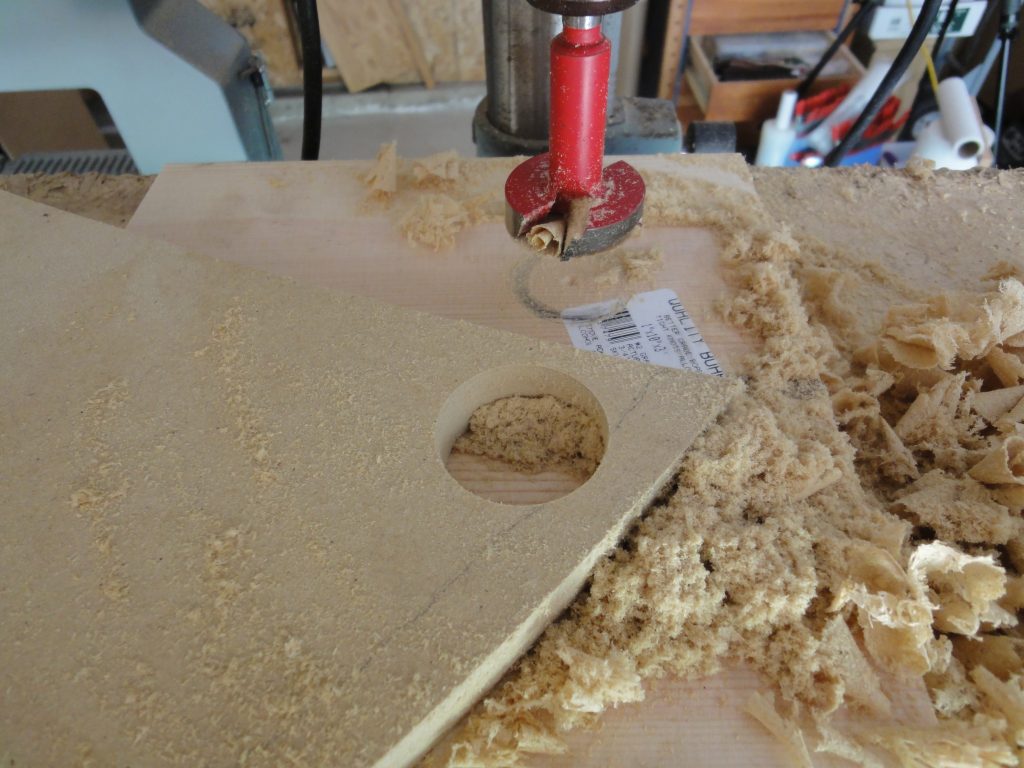
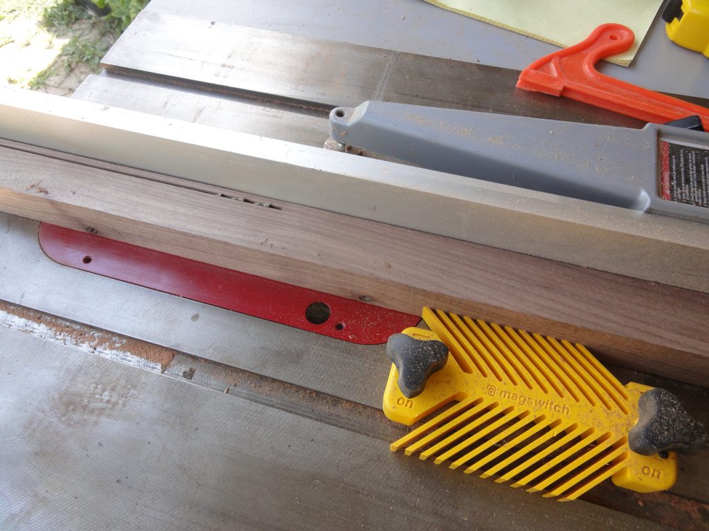
I suppose now would be a good time to mention the new tools and materials brought into the mix. There are a number of schools of thought on how to cut strips. For very long boards (16’+) that some people get so they can have single strips, they use a long bench (or the strong back itself with a sacrificial board) and then rip off the strips using a circular saw with a fence. Of course this works on shorter boards too. The other common method is to use a table saw. Since I’ve got one and none of my boards are over 9 feet, I’m comfortable using it and decided on this route. So, a table saw (I’ve got an old Delta but if/when I need to replace it a Saw Stop is a no brainer), a Magswitch quick release feather board, some plastic wrap, a roll of floor protector paper, a drill press (again an older model Delta bench top model) and a larger (around an inch and half or so) Forstner bit. Also I used a variety of clamps that I already had on hand. Some spring clamps and some small bar clamps. Blue painters tape was used as a glue shield and will be used for a lot more later on.

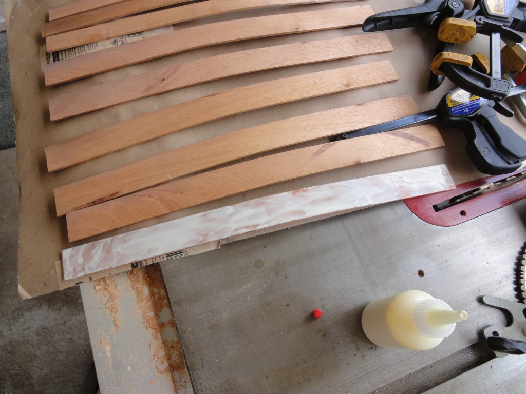
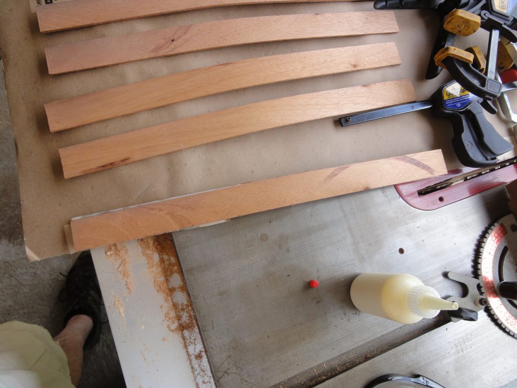
To begin with I found a longer piece of hard wood, cherry in this case, that I had on hand and decided to make my stem pieces out of it. The color should be similar to the spanish cedar when completed, but will darken a bit over the years too. These have to be bent and you’re not going to bend a 1″ or larger board so first task is to slice this into 1/8″ thick pieces and then cut these pieces into a longer piece for the bow and a shorter one for the stern. One of them split however the remaining pieces are still more than enough so I just discarded the split one.

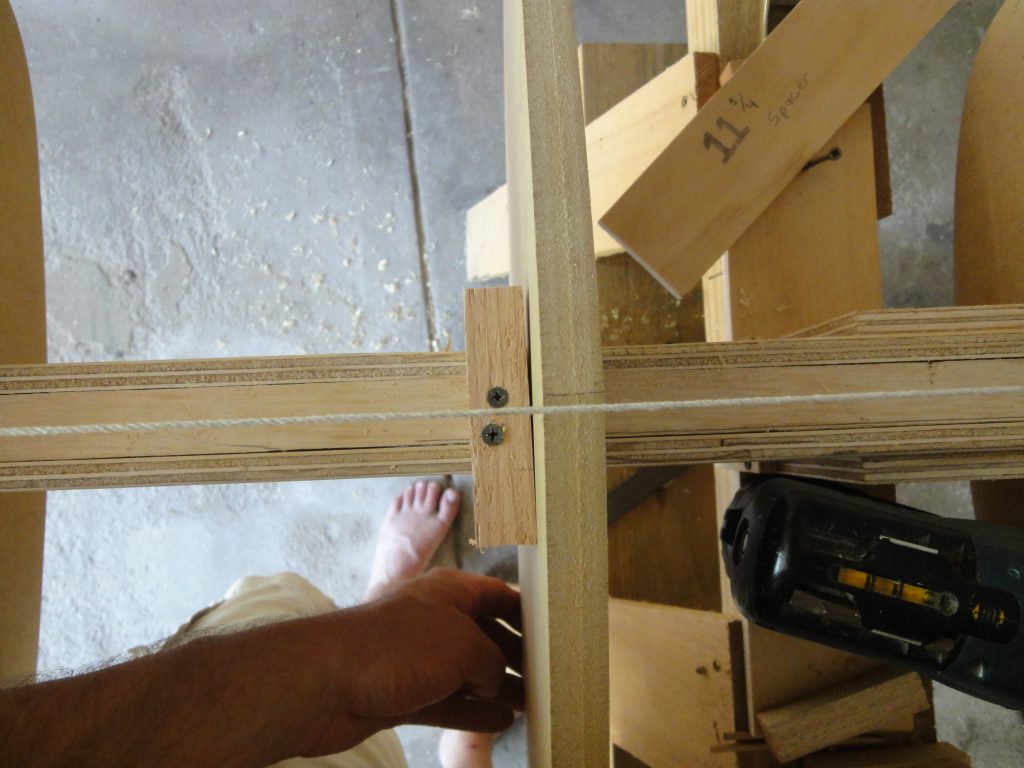
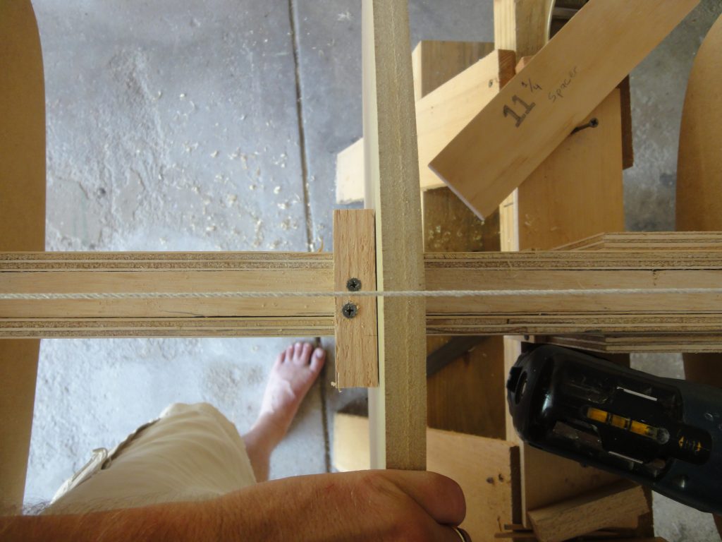
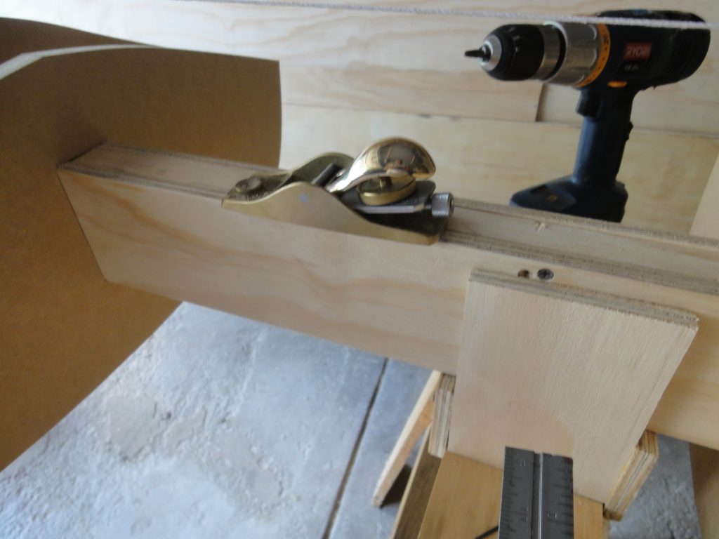
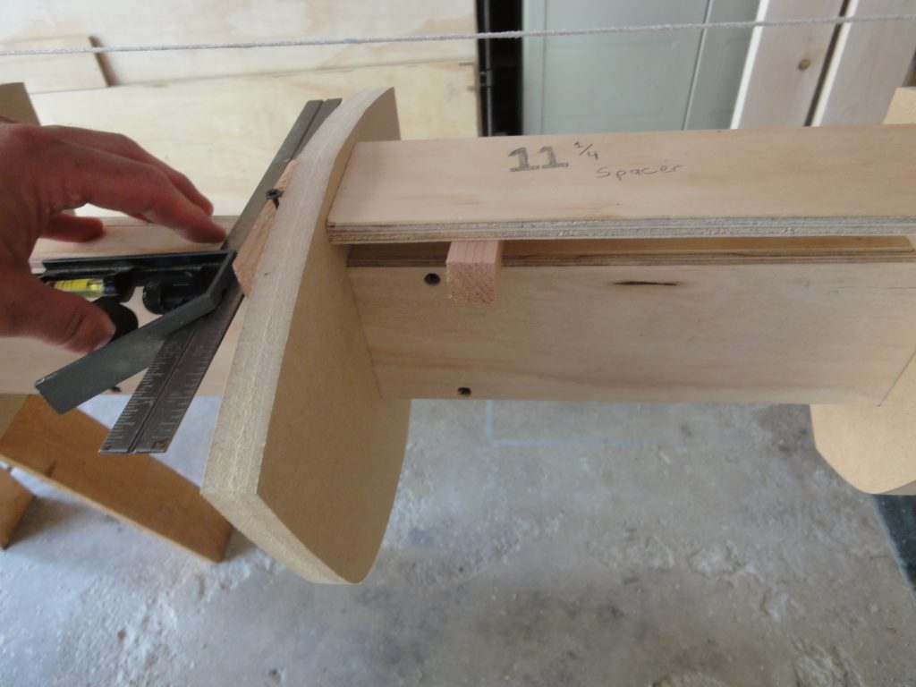
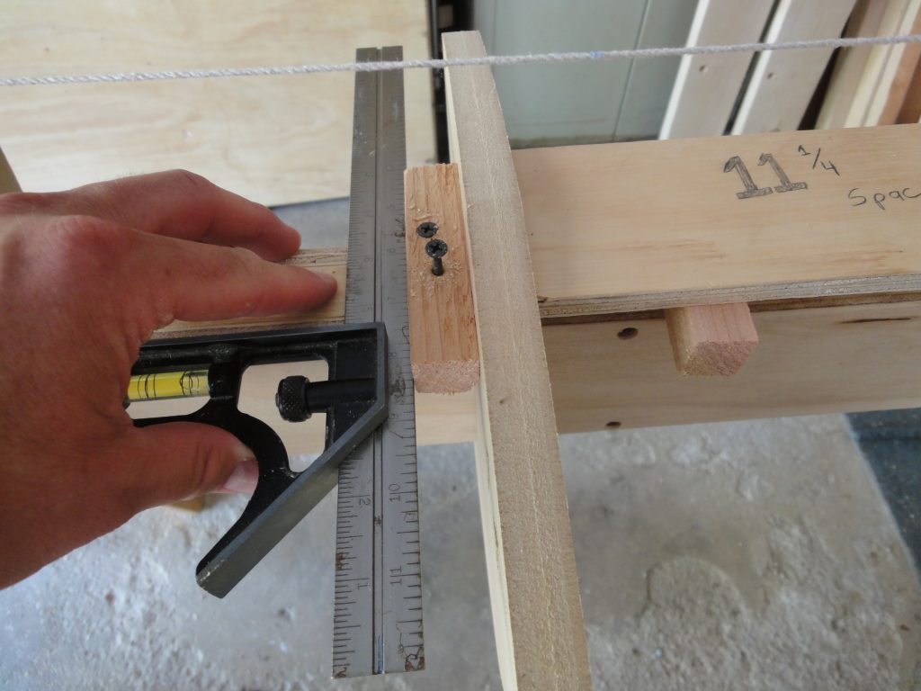
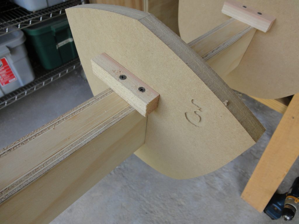
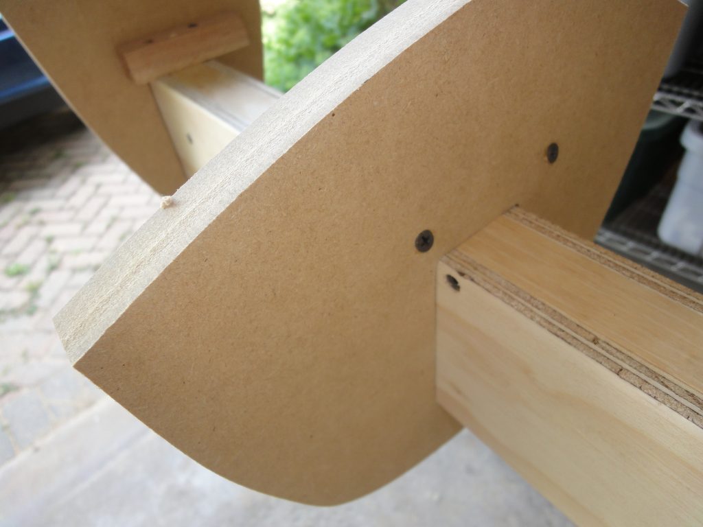
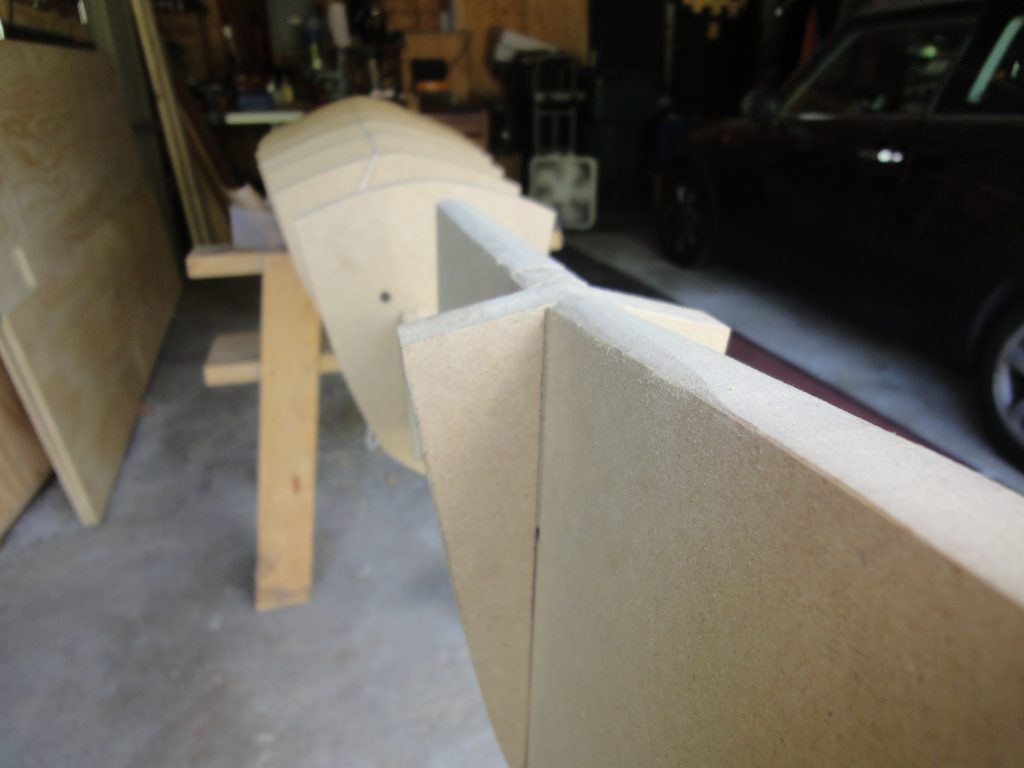
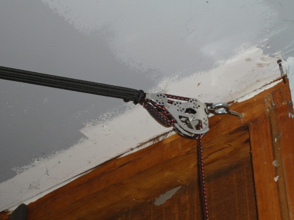
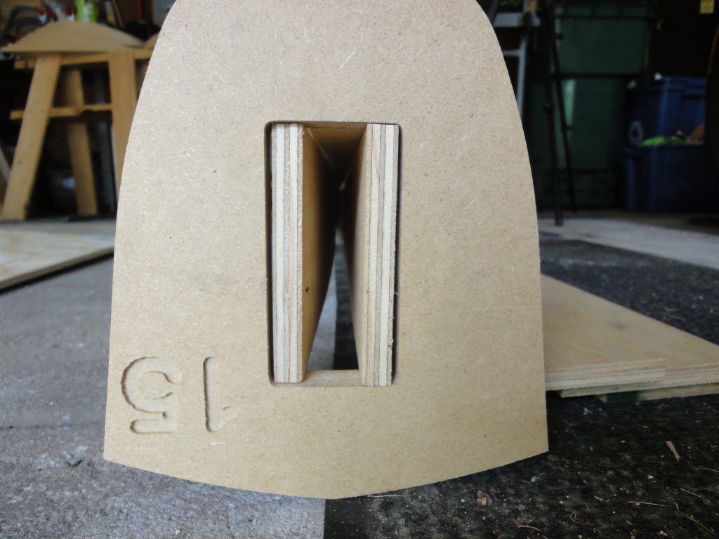
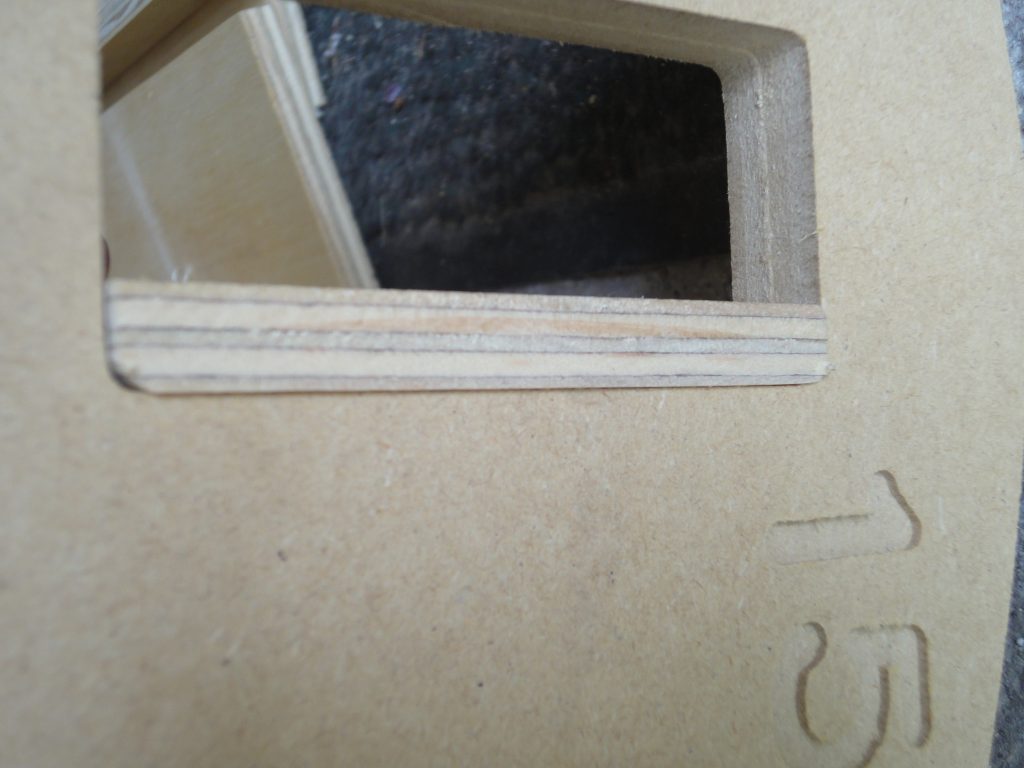
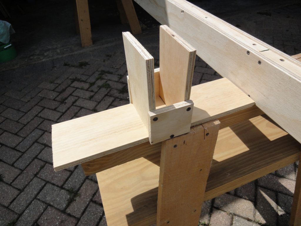
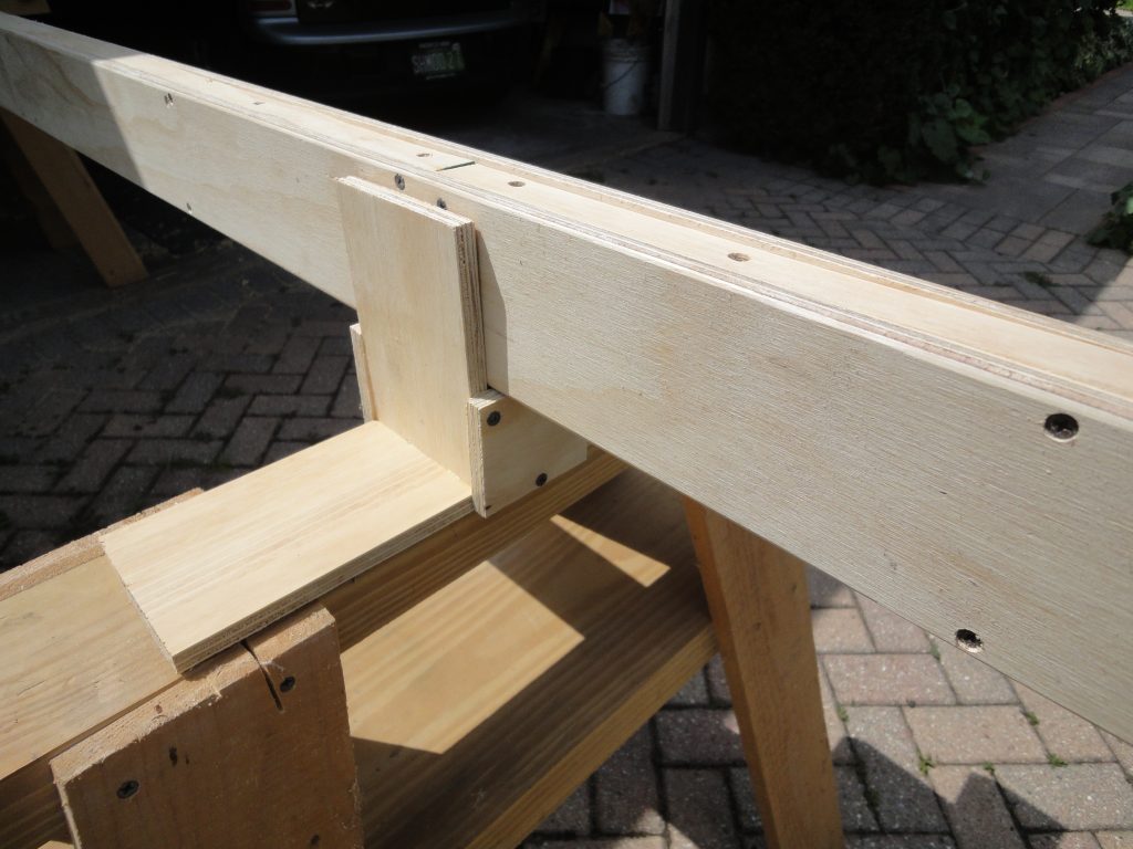
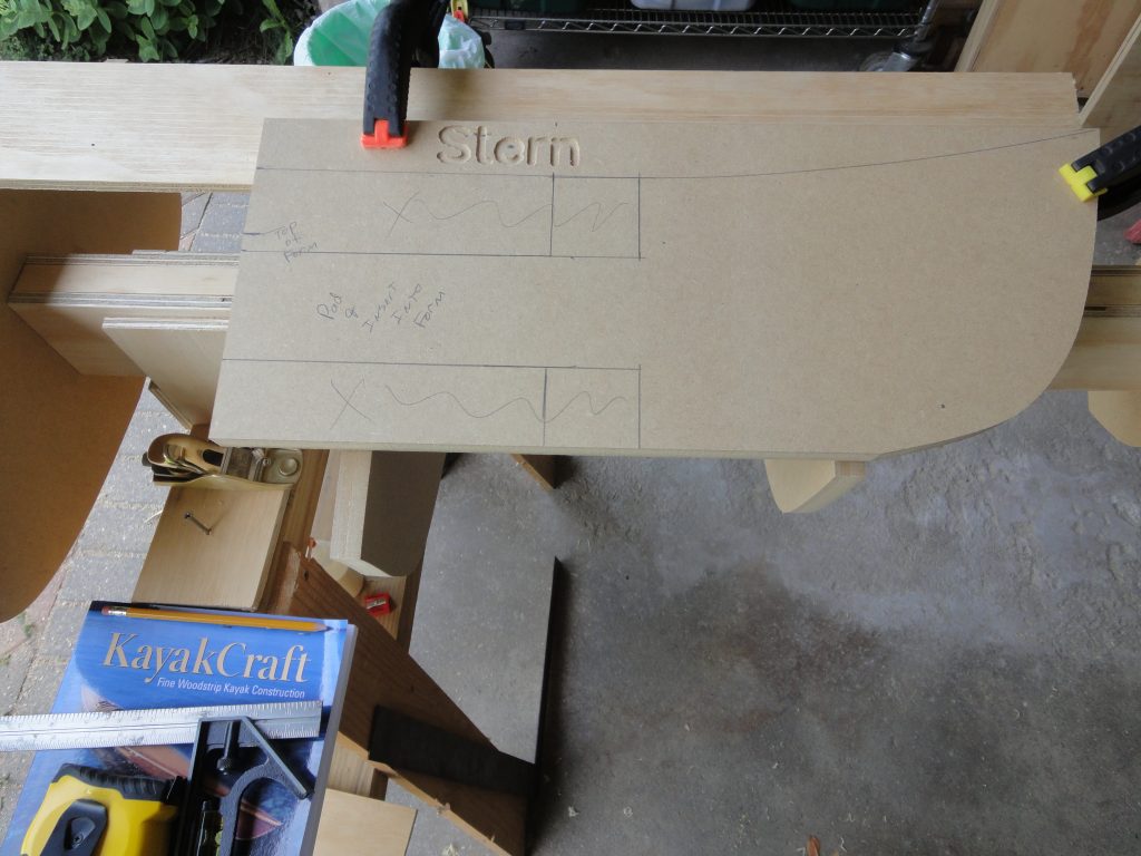
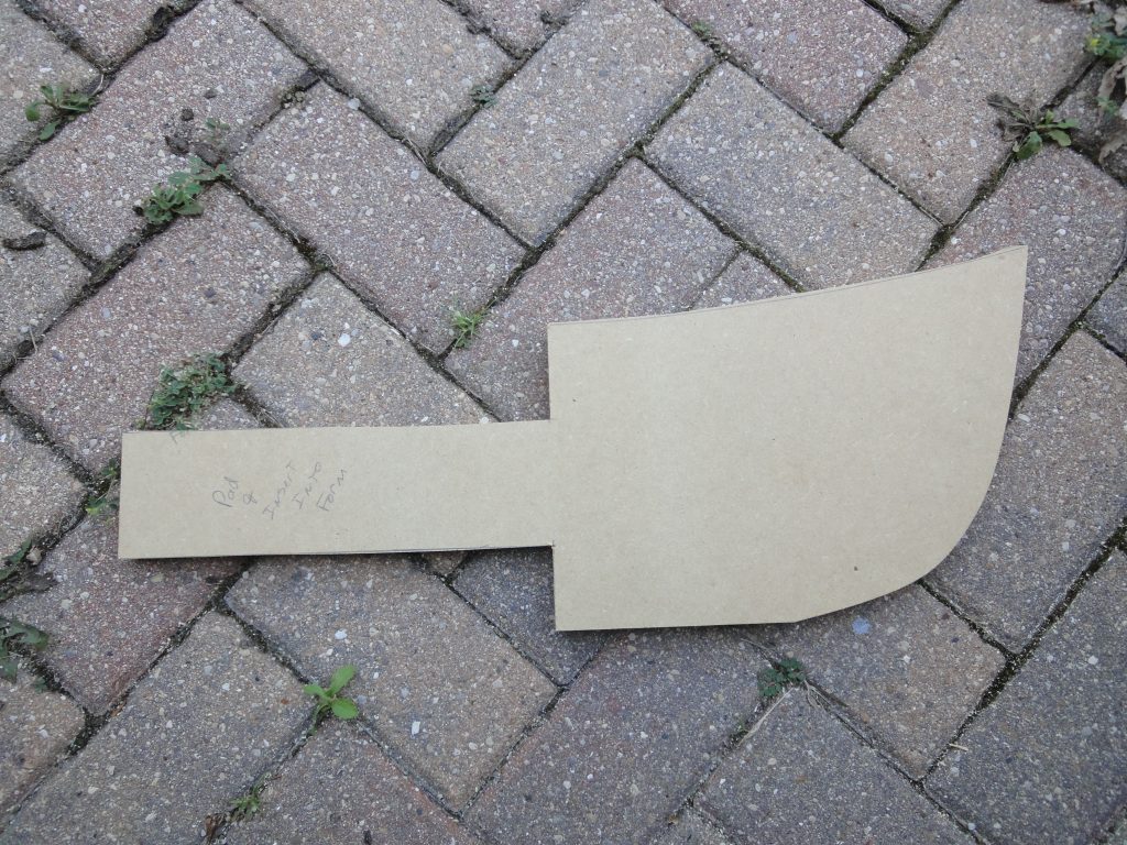
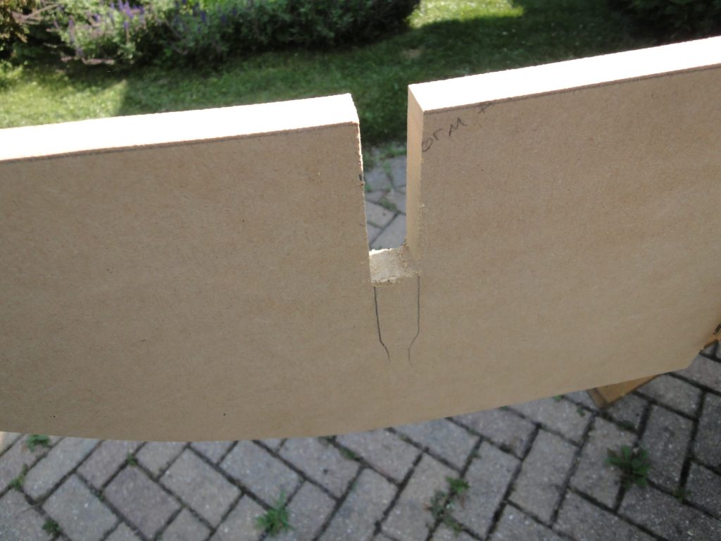
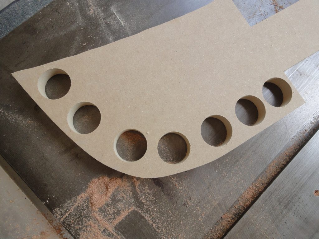
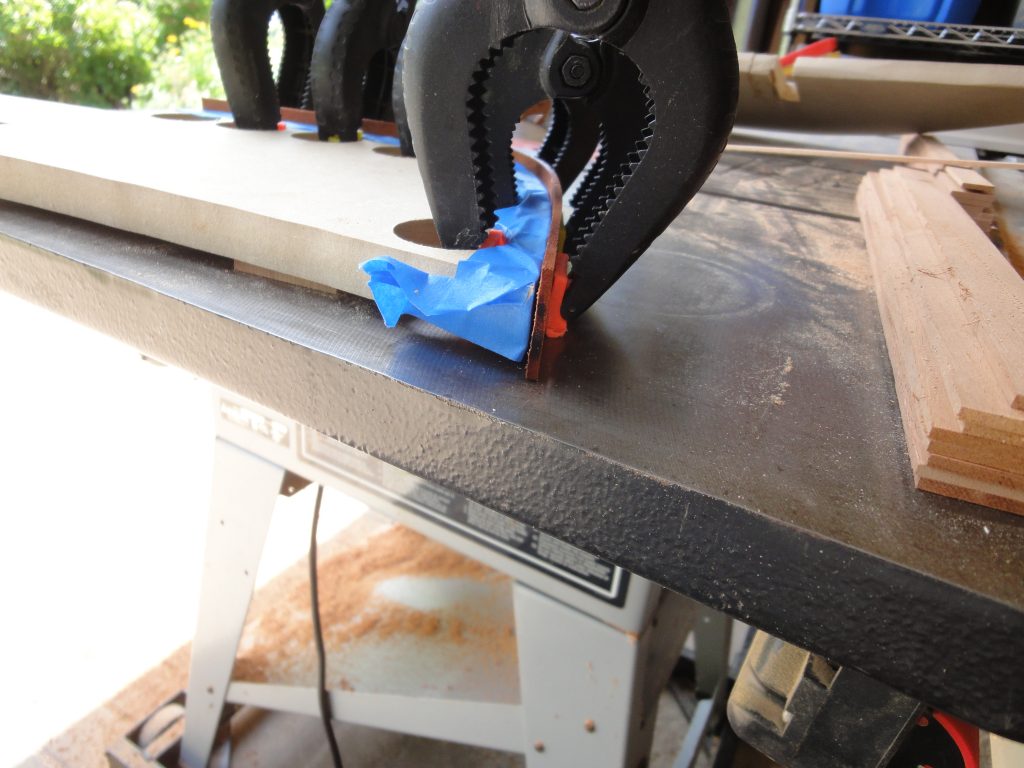
I need to attach these strips to the forms and also need a way to clamp them in place. Some holes drilled in the forms provided this.

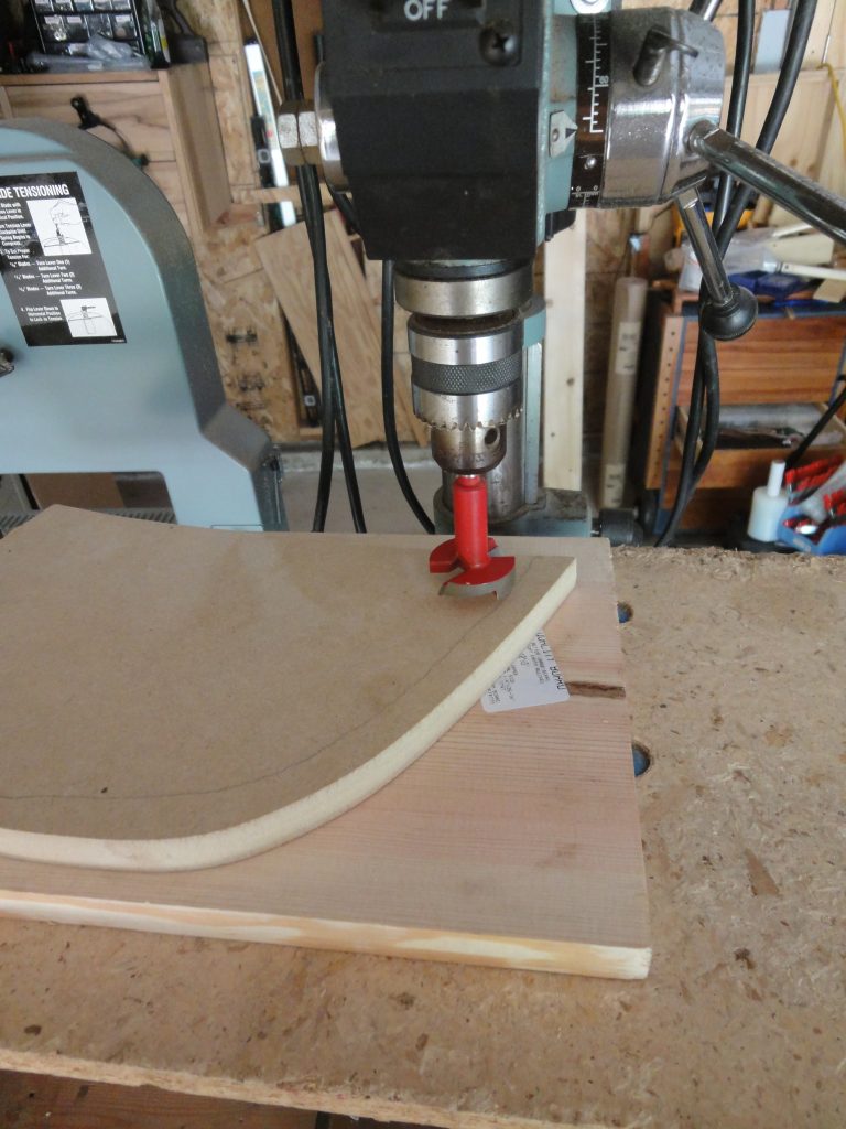
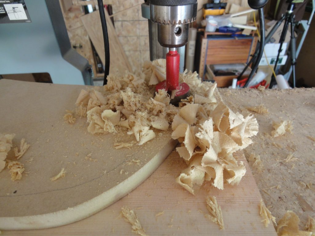
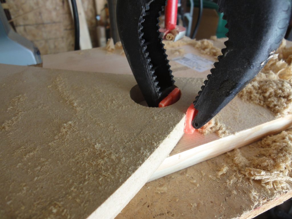
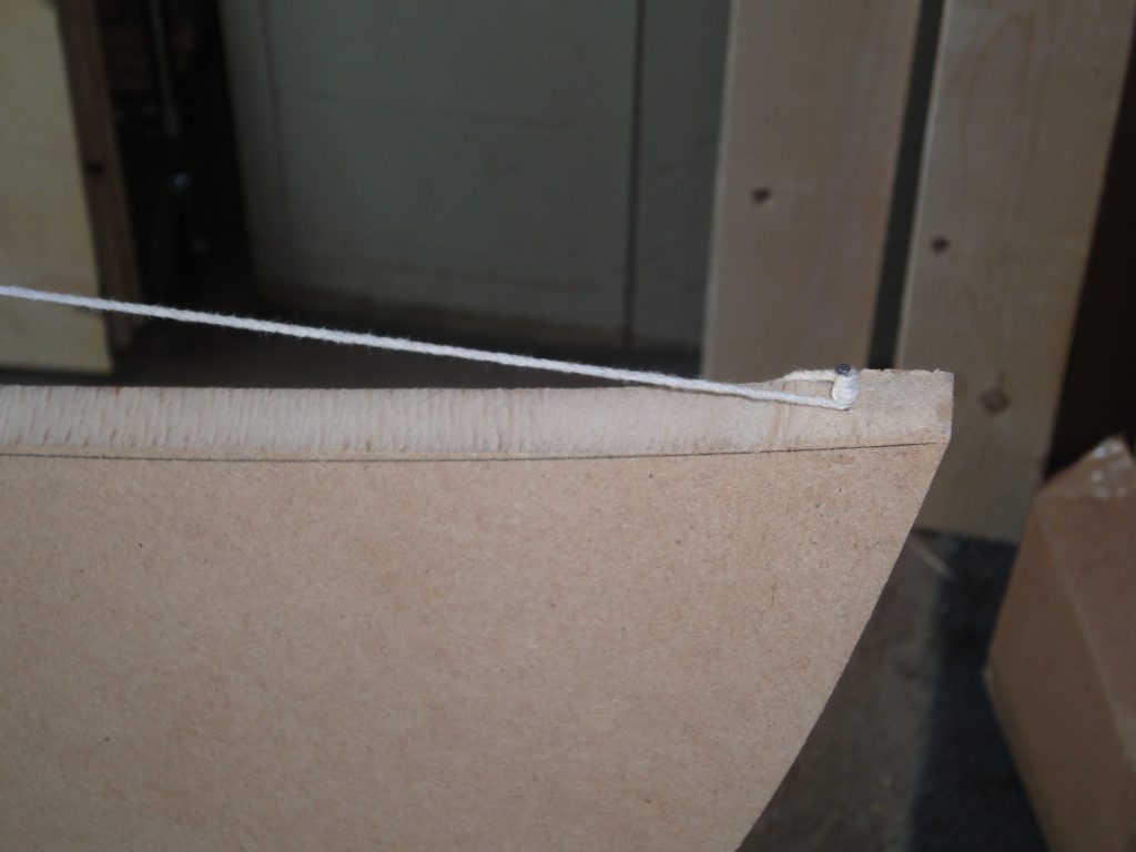
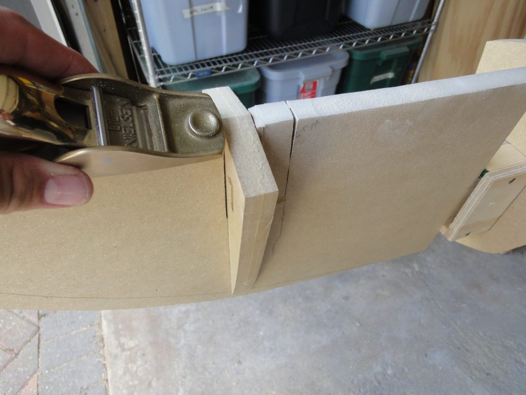
To test, a single piece was bent around the form. It was having trouble making the tight radius and I was concerned about breaking it. To help I wet the piece down. A few other options would be to steam it or to use a hot air gun on it. In this case I was lucky and simply getting it wet gave it the extra flex I needed. The pictures illustrate the use of the clamps and the holes.

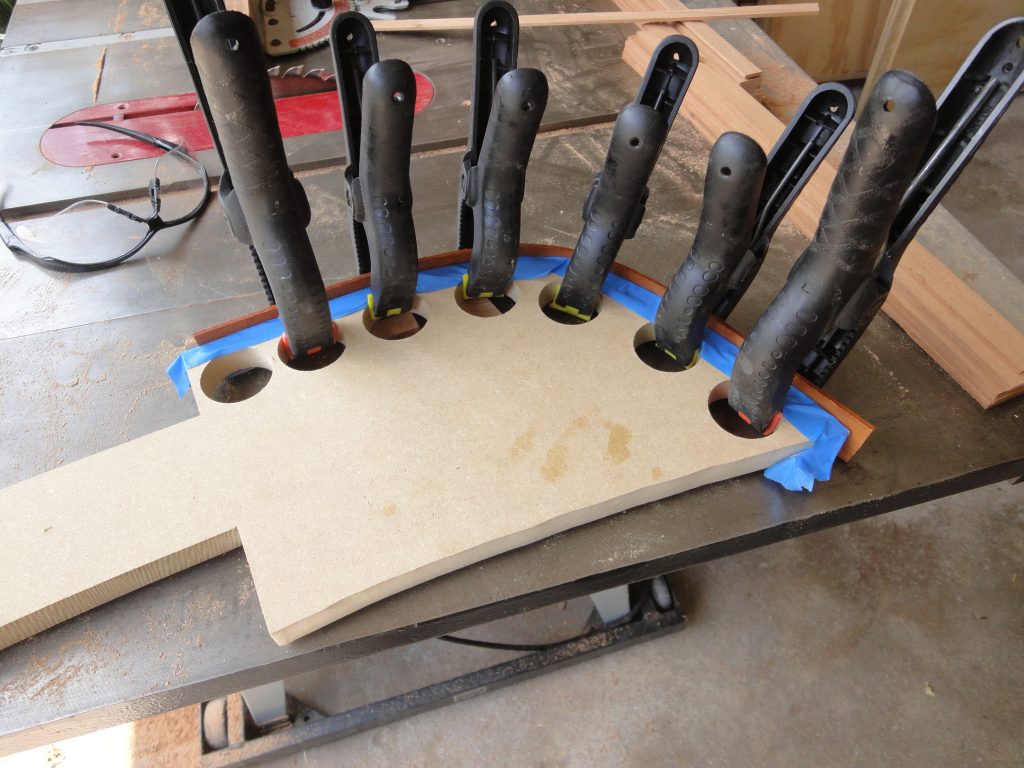
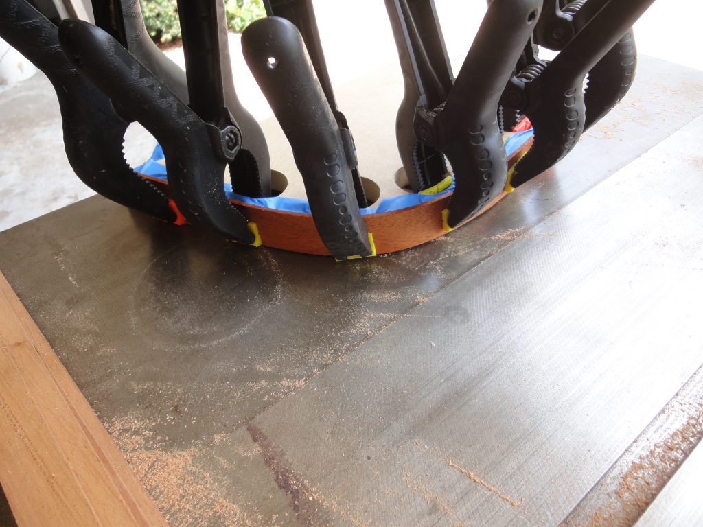
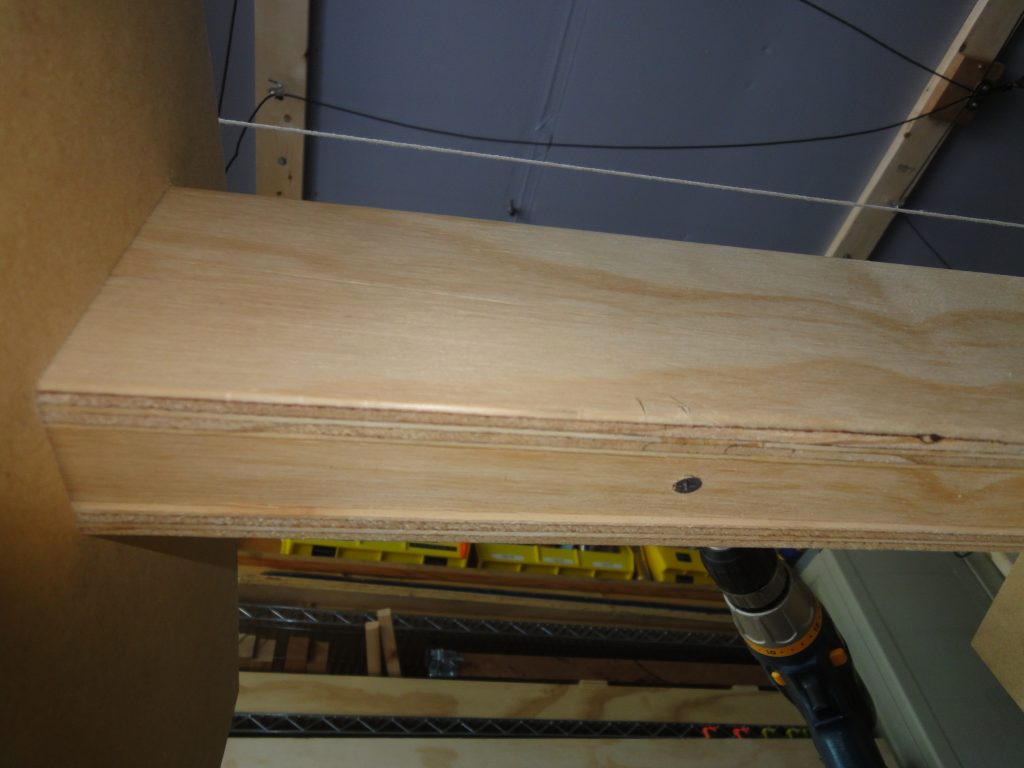
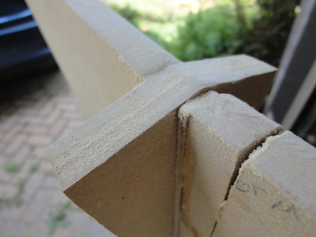
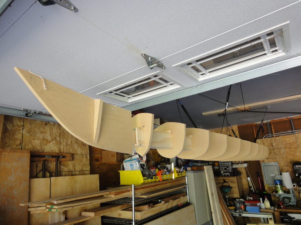
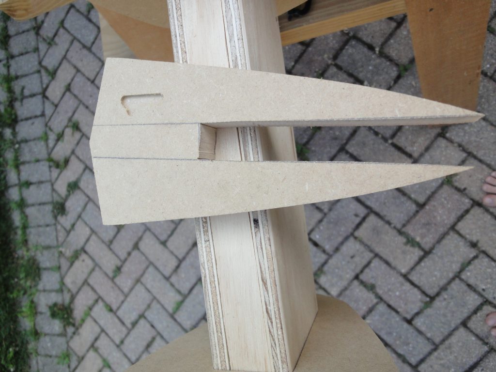
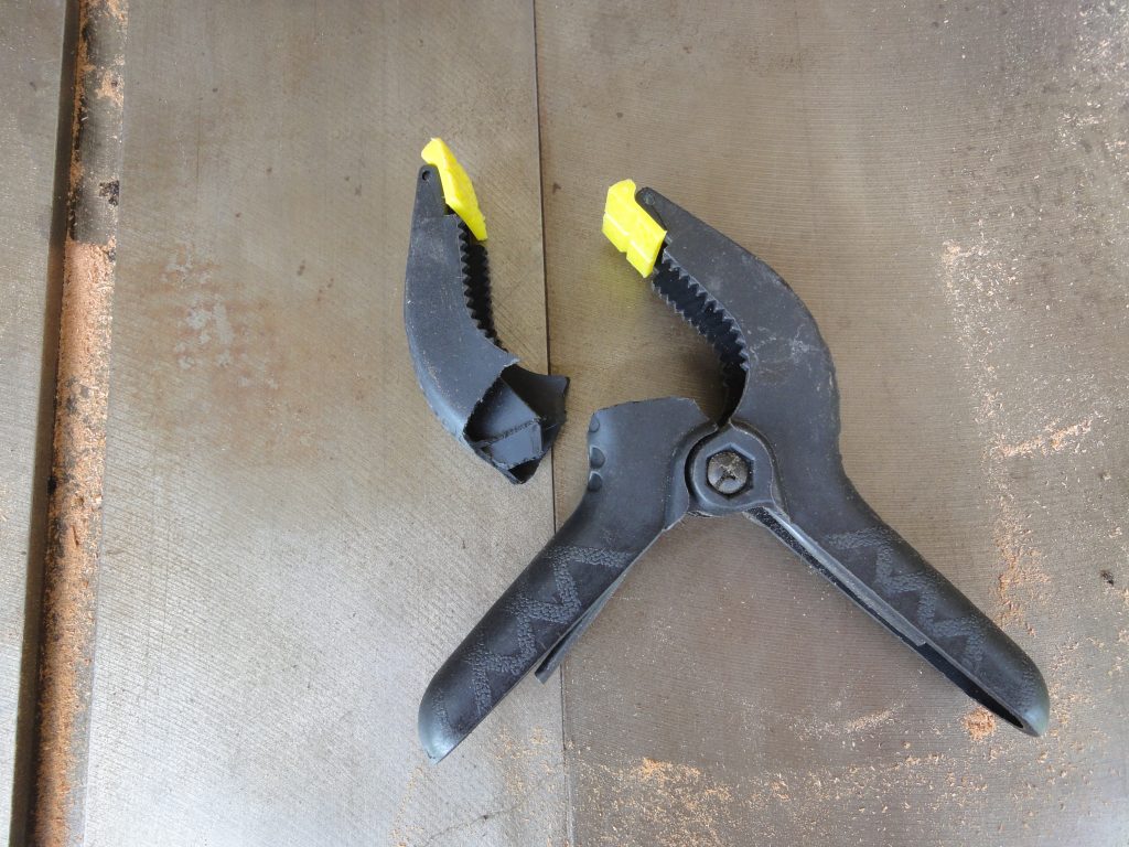
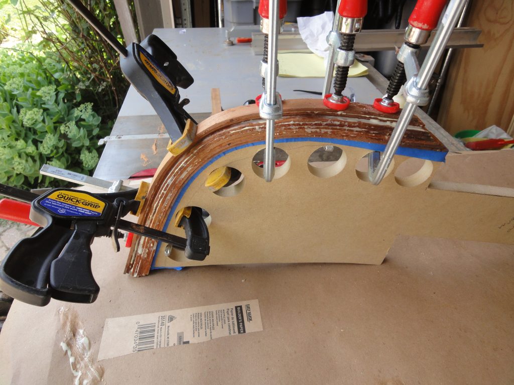
I did a test with all the boards at once next. Wet them down, applied clamps, etc. It was much harder with all of them. I found this out the hard way when my back was turned. A loud snap followed by the sound of pieces of plastic falling. As a result of the broken plastic clamp I dug up my metal bar clamps and mostly used those instead. Much stronger. After allowing this to sit for a few hours, the clamps were removed and the wood had already started to take the bend.

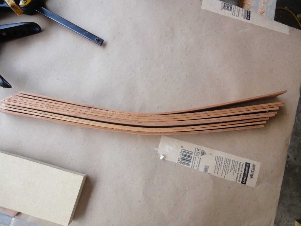
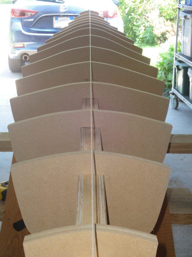
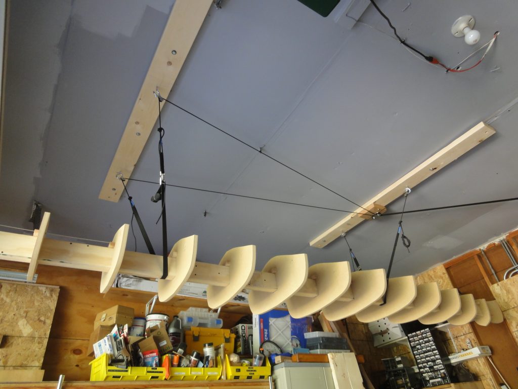
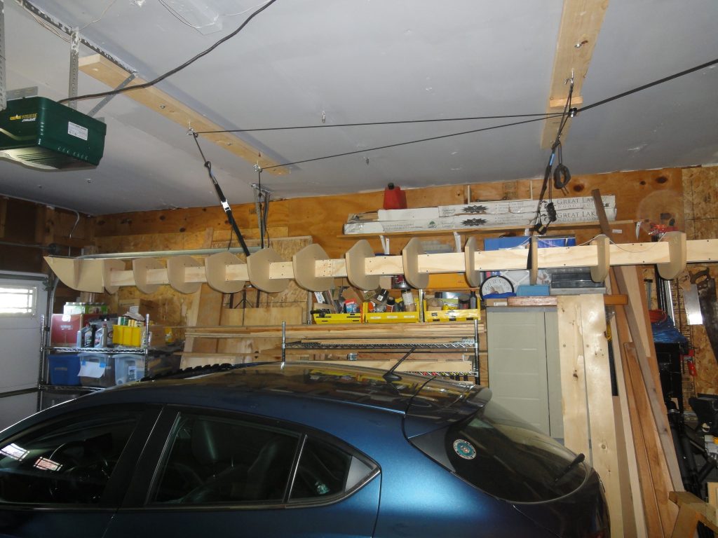
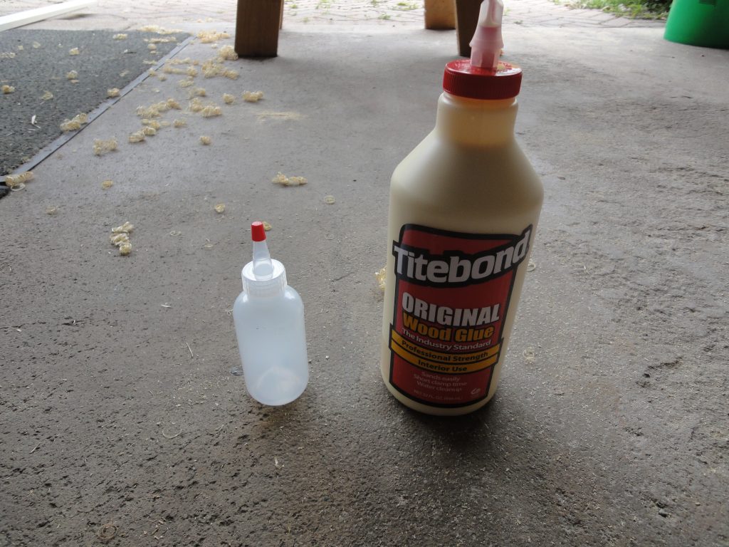
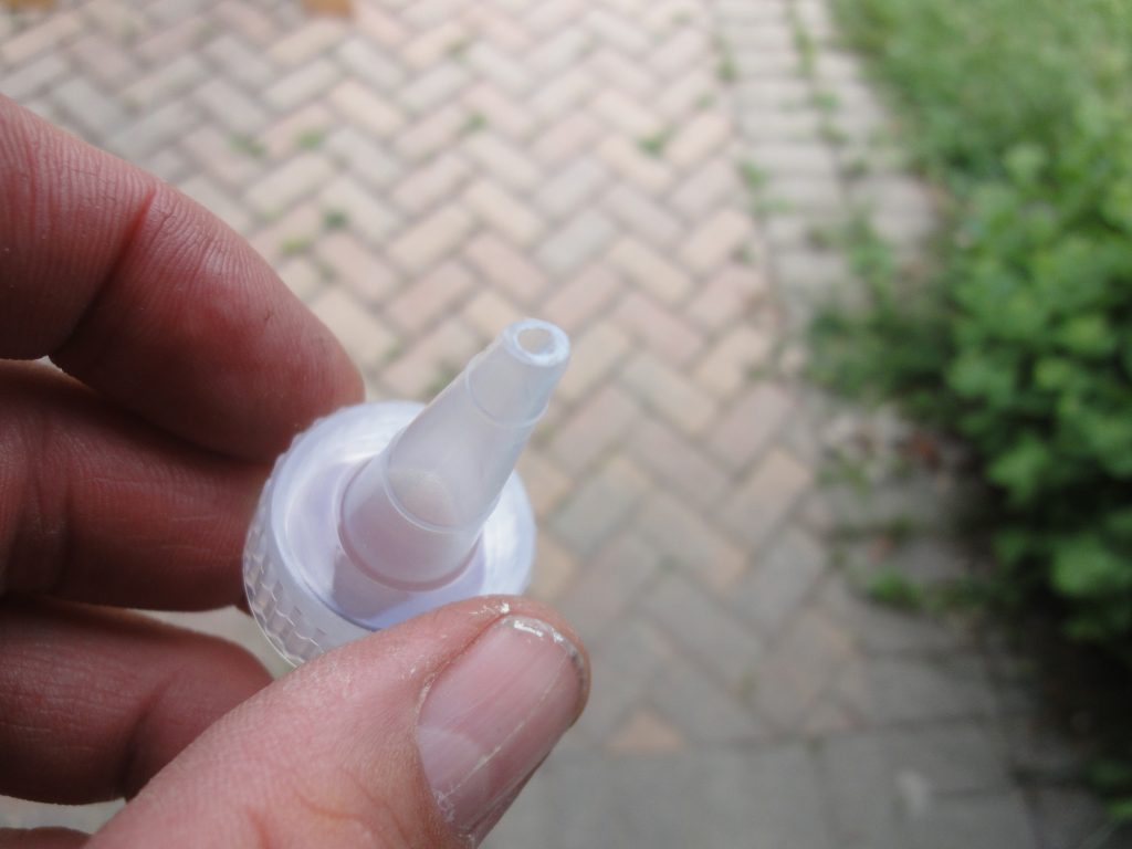
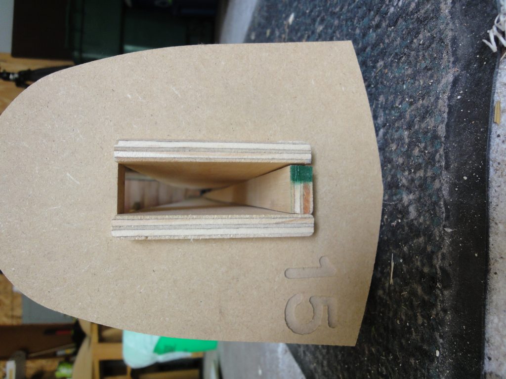
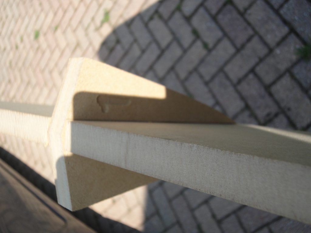
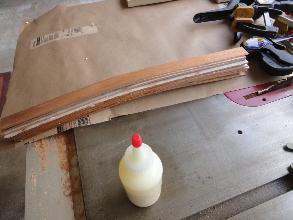
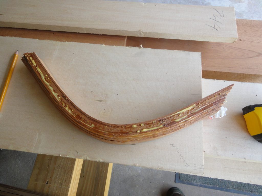
The next step is to glue the pieces together and place back on the form. I verified they were dry first and then a liberal coat of glue was put on each strip, they were stacked together and with a bit of coaxing I finally got them clamped in place. With the glue acting somewhat as a lubricant they want to shift around while clamping. Of course the whole time you’re racing against the open time (how long until the glue starts to set) of the glue. I left them for a few hours to setup up and then checked the assembly and found it was holding the shape pretty well. After the photo was taken I clamped it back in and will leave it there until the next time I can work on it.

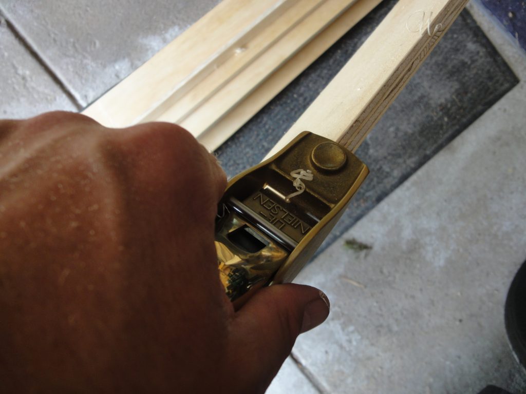
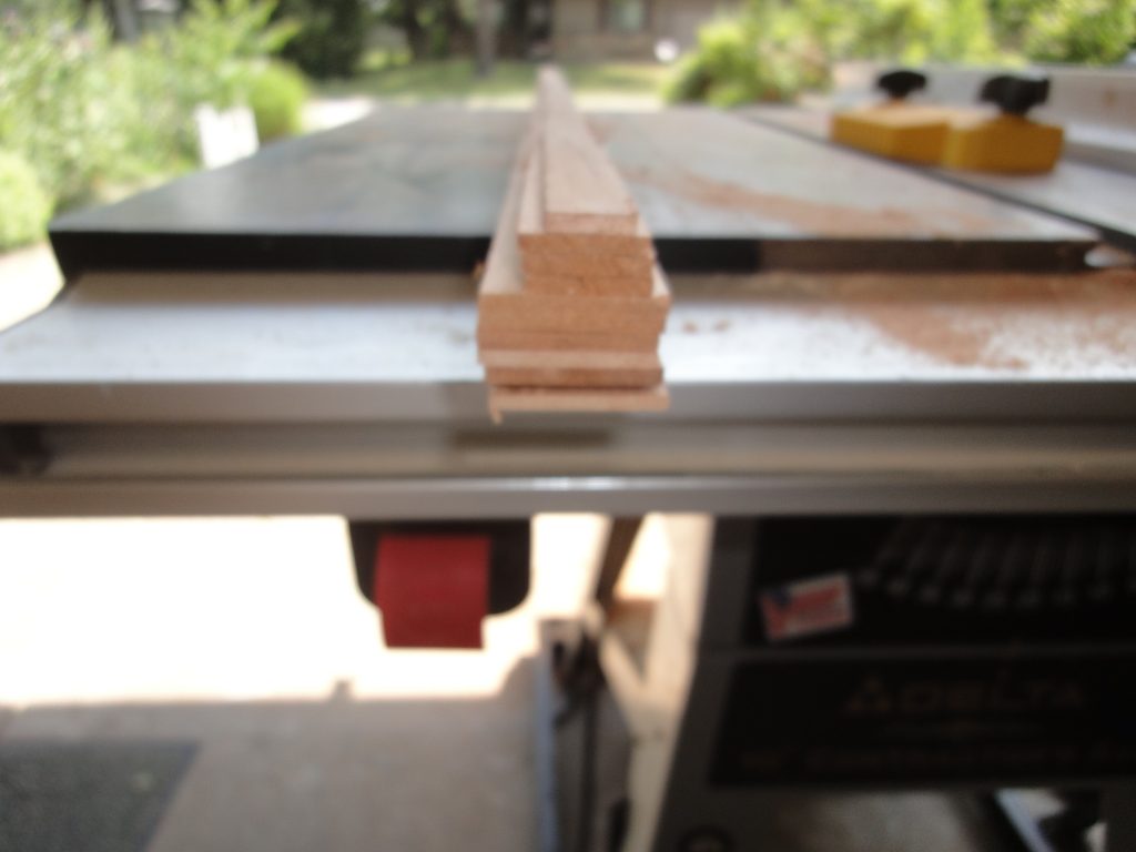
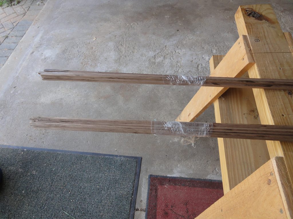
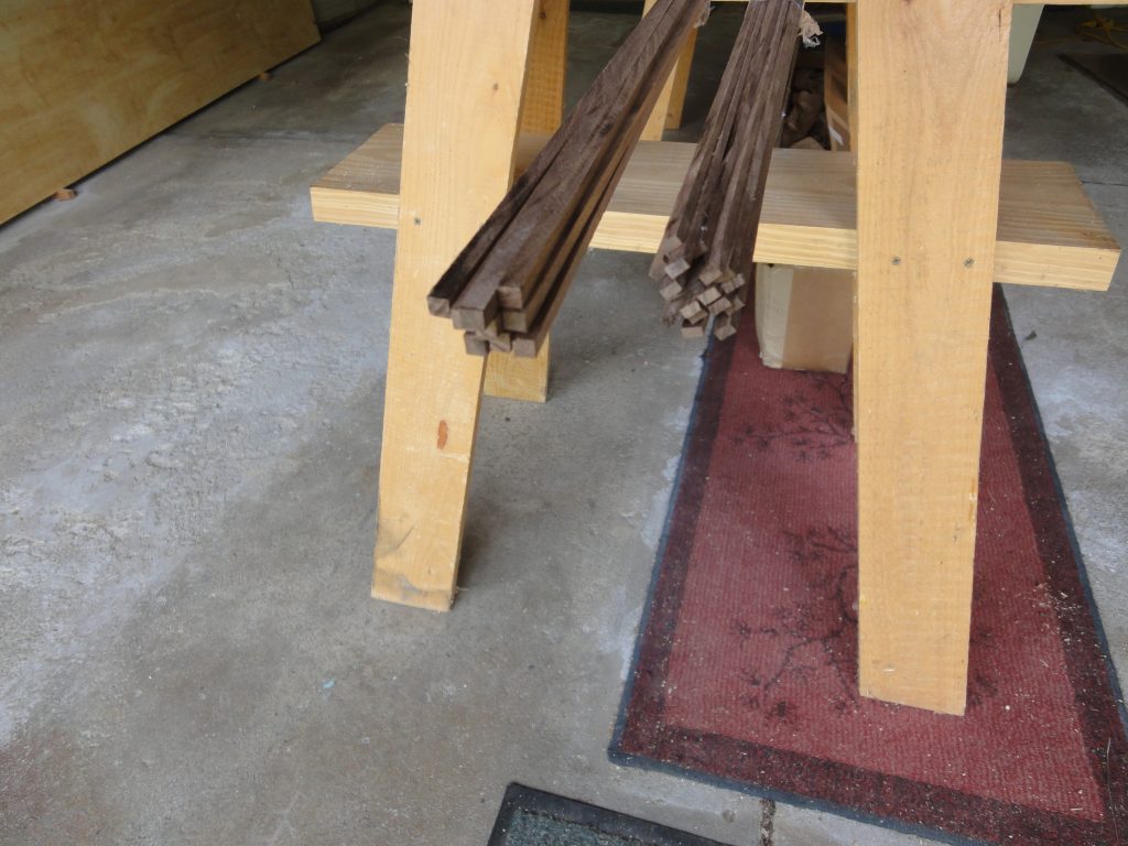
While this was drying I started on the strips. The walnut was first as it was a relatively small piece and I needed all 1/4″ x 1/4″ and 1/4″ x 1/8″ strips which will be used for accents. Over all the cutting went well with only one 1/8″ strip breaking and unfortunately also getting caught up in the blade and thrown back in a kick back situation. I had enough left over walnut to re-cut that strip. Essentially the block was ripped into 1/4″ thick lengths, then each piece was turned on side and 1/4″ or 1/8″ strips were cut off of it. The resulting bundle is not intended to be used in any particular order so I just gathered them and used stretch wrap to keep them together.

Next time I plan to glue up the pieces for the bow and start cutting the basswood strips. Most of the basswood is fairly consistent on grain so it’ll be mostly straight forward cutting. I’ll put together a better sequence of pictures at that time since they will be reflecting the majority of the strips and sizes that will be used.

Aligning the Forms

Today showed little visible progress but actually was quite productive in the prep work category. The goal was to get the forms permanently on the strongback since I could now lift it out of the way. While in previous posts I showed the forms on there, they were just slid in place and not aligned or all consistently spaced out.

I stared with attaching a small nail on the center of the tip of the bow and stern. A string was attached to both and pulled taut. Sighting down the string I was able start to check the forms for alignment. To ensure I was viewing the right spot I used a pencil to put a line right at the peak center point of each form.

Some small dowels were inserted along with a few screws to pull the bow into alignment. Once the bow and stern were straight the forms were next. They each fit fairly tight to the strongback but being wood, the strongback is not as rigid (straight) as an aluminum beam could be (but a heck of a lot cheaper) so there is some adjusting that needs to be done. When a form is out of alignment it’s pretty obvious.

The steps to align a form are not difficult. First I look to see just how much it has to move. If it’s off just a tiny amount there may be enough play to adjust it. If not, then I use the block plane to shave off a little bit of the beam where the form goes. I don’t shave the whole beam, but rather just the corner areas that are tight to the form. When a little is shaved off the form can now rotate just a tiny bit. I recheck alignment. If still not good I repeat until the form can rotate into alignment.

Once the form is aligned you need to some how keep it that way. To start, I cut a bunch of small blocks. About 3/4″ x 3/4″ from some scrap lumber. A spacer block of 11 3/4″ was used to determine the next form placement, that was slid into place and then the form was moved against the spacer block. These blocks were then moved against the form, aligned perpendicular to the beam with a combination square and two screws were used to hold them to the beam. The form was pressed tightly against the block, rotated into alignment (if necessary) and then two screws were used to attach the form to the block.

The process is repeated for each form until all are in alignment.

By far most of today’s work was in aligning the forms but I also fixed my first mistake and started to plan and do a bit of the shaping. The oops was the placement of form #1 on the bow. As I stated, the prior alignment of the forms was just a “let’s see how they look” and I should not have mounted #1 yet. After doing the precision placement of each form I found I was about a full inch off. So a new notch was cut and the waste piece was glued into the previous notch. It isn’t really necessary but helps a tiny bit with structural integrity, especially as a backer block for the narrow bit that was left. The top point of form one should be even with the pencil line when form 1 is finally aligned.

The bow and stern will end up with an inner and outer stem or keel. I plan to use the bow and stern forms to create the outer keel, then with the outer as a template, create the inner and then finally trim off the part of the form where the inner will go. The reason for the inner stem is to have a place that the strips can be glued to. You can’t attach them to the form or the form would never be removable. The stem itself will just sit against the form but not be attached to it. The pencil line is an approximate estimate of about the size of the stem.

Finally the bow and stern have to be shaped to match the angles of the eventual stem (comes to a point) and the surrounding and overlapping forms. So the top has a small point in the center that has to be formed at form 2 and 1 and then it should curve over to a point at the tip. You can see this somewhat in the drawings and the video demonstrates the approximate angles that I’ll need to move the plane to cover this area. The final image is my first shaping and sanding. When I can shape all the way to the point I’ll finalize this rolling bevel, but this won’t be until I have the stems made.

The angle of the plane will go from pretty much vertical to almost horizontal to match the top of form #2.

At this point I decided the 90+ temperatures were quickly sapping my energy so I’d clean up and call it quits for today. This was my first try at using the lift to raise up the kayak forms. I’ve still got it sitting below the door but this is fine for now as it clears my car. The straps could have been placed a bit better too but this will work itself out as the kayak starts to take shape. Standing back and looking at it and I can already see my completed kayak hanging there.

Third Class Today and Some Hanging Around

I took the third kayaking class today from REI. This was a smaller group, only 4 of us plus the instructor, Matt. He did a good job teaching us bracing and edging. Being still somewhat new to kayaking these terms weren’t something I was familiar with so I learned that bracing is essentially slapping the water with your paddle when you’re about to go over in an effort to push you back upright. Edging is what it sounds like. Tilting the kayak on edge and paddling. It lessens the amount of kayak in the water making it easier to paddle and quick to turn. This is very common, we were told, for those getting in to white water and such. It can also be useful to make it easier to paddle. How fortuitous as we got most of the way down the lake when a big wind came up producing, for the small lake, decent sized waves. While practicing the edging I had my paddle in and started going over. Unfortunately with it in I had nothing to brace with and ended up wet exiting. Having learned and practiced these a few weeks ago I did it quite well and using the assisted method I was back in my kayak in literally a minute or two at most. So we then paddled across the lake, parallel to the waves and then turned and had to go into them/the wind all the way back to the launch point. It was a great workout and when I was up on edge I could feel a bit more speed. I won’t say it was easier as this is still a new paddling technique for me but with time and practice maybe it will come more naturally.

However, honestly I really don’t think I’ll utilize edging that much but bracing in waves is something I can see definitely taking advantage of. After class I got measurements on the 57″+ cockpit of the Pungo model. I determined where leg/knee clearance would be for me and pretty quickly figured out that I need 36″ from seat back to front of the coaming. Add in the distance from seat back to the rear of the coaming and that will be my size. Roughly 39″-42″. Width wise the small cockpit of the Tsunami model I used was fine at 17″ but I’ll probably stick with the 18″ on the plan specification.

Over the last week or two I did a lot of cockpit and sprayskirt research. A very valuable site is Skirtfit.com which has a LOT of cockpit dimensions listed on their site. I went through literally every brand and model and recorded a good sampling of width/length dimensions from about 30″ up to just over 50″. The Bear Mountain Resolute calls for a 30.5″ x 18″ cockpit. The Old Town Cayuga has a 42″ x 19″ cockpit according to Skirtfit.com however according to an old 2008 PDF (the Cayuga is discontinued) page 6 and a mention on REI’s site it lists the cockpit at 40″ x 16.5″. Any of these dimensions should be fine for me. Using a site like Seal Skirts I can enter the make and model so I put in the Old Town Cayuga 110 and it said that I need a standard sprayskirt of their sizing 4.2. So this tells me that as long as my cockpit is around the same size that I will have no problem finding a spray skirt.

I was also busy this week ordering more of the supplies like the fiberglass and epoxy among other things. When those supplies get used I’ll discuss them. For now the other item I got is the Harken Hoist I mentioned last time. I looked into other ones and the Harken model seemed to have the highest lift. Many had fairly long hooks and such that you anchored to which loses storage space above the door. The kit seems a bit light for what you pay for it but I found pretty much all good reviews and while I could have cobbled together pieces and done something similar for less, that would be hours more research and shopping and frankly I’d rather put my time towards the kayak and not into lifting methods.

The install was pretty easy. Use a 2×6(not included) to anchor to your rafters then everything anchors to the 2×6 and to your wall. The hardest parts were ensuring I was putting the lag bolts into the rafters and trying to tie off the lines at a consistent height. I still don’t have the line lengths perfect but it’s good enough for now. Once I have the kayak shell and not just a beam to work with I can get a more accurate length. When I first tried raising the beam I ran out of room when the block and tackle mechanism ran against the eye bolt. To fix this the lines were retied shorter. The beam still tops out below the door but this is partially because I’m lifting what amounts to a 2×4 instead of the full size 25″+ kayak. The larger size will take up a lot of slack and should sit much higher although I may still have to adjust the lines a second time.

While the lag bolts should be sufficient, for an extra measure of safety I plan on putting long through bolts from the 2×6 through the ceiling and into a second board on top of the rafter joist. This second board can be screwed into the rafter from above for an added level of anchoring. It may have to wait for a cooler day as normal summer days are 130+ in the crawl space attic and the conditions up there are such that it can get dangerous fairly quickly.

A quick video showing the system ready for use.

Strong Back (or is it Strongback) ?

Two words or one? Don’t know and an internet search shows wide spread usage both ways. I’ll try to pick one and stick with it. Today’s posting is about building the strongback. From start to finish (including pictures and documenting) it took about 5 hours.

First, let’s start with the tools I used. Not pictured is a bench top band saw. I also used a cordless circular saw (shown later) with an edge guide, some larger spring clamps and a box of 1 – 1/4″ screws, something I had left over from previous projects. The rest of the tools I used are shown below.

First is a low angle block plane from Lie Nielsen. Quite a number of fittings will require slight adjustments to boards and strips. I do not own a small plane so ultimately this is something I probably would have purchased even if I wasn’t building a kayak.

Next is a Japanese style saw known as a Ryoba. This double sided saw has both ripping and cross cutting teeth and cuts on the pull stroke. They’re relatively inexpensive and very easy to follow a line compared to a “western” style push saw. I got this earlier this year for a different project and find it’s now my go to saw for just about anything being hand sawn.

The third picture is some of general tools that most people would have. Cordless drill, counter sink bit, pencil, sharpener, tape measure and combination square. Nothing special here.

Fourth is a bunch of clamps. I already have larger spring clamps and got these four inch clamps mostly for temporarily clamping the strips to the forms. A cheap bulk set, again nothing special, just enough to do the job.

Last is a fresh quart of Titebond wood glue and a smaller dispenser bottle. Trying to control the larger bottle is not easy and the opening doesn’t allow for fine control on the narrow strips. The smaller bottle allows you to cut the spout to whatever size you want. I went with the smallest cut I could to get a relatively fine line of glue.

Let’s get on to the project. The strongback is essentially a straight solid surface that your forms mount to and allow for the alignment of the forms and also hold them in place during the building. I had already designed the forms to have a 2″ x 4″ hole in the middle, that when placed on the strongback, would align the forms in the correct positions.

To start, I cut a bunch of 4″ strips from a sheet of 1/2″ plywood and then since the plywood is technically slightly less than 1/2″, I cut some oversized 1″ strips. (2″ gap – ~1/2″ left side – ~1/2″ right side = ~ 1″ space)

There was one problem immediately apparent (and anticipated). The CNC cutting process uses a round cutting bit. This means that it can’t get into the corner of the form and thus you end up with rounded corners. You can see this below in that the two 4″ pieces don’t sit tight to the sides.

This is easily rectified by running the block plane down the corner of the plywood a few times to round it over slightly. Now the boards fit tight.

I could now fit in the slightly over 1″ wide strips to effectively create a beam. I screwed the 4″ pieces to the 1″ pieces being sure to stagger the joints and also screwed a reinforcing board (inside) across each joint. The screw heads were counter sunk to avoid interfering with the forms when sliding them in place. Reviewing the drawings and plans, it shows station 2 through 15 would need to mount to the beam. From one station to the next is 12″. So, 15-2 = 13. Thirteen times 12″ (3/4″ form, plus 11 1/4″ space) = 13 feet. My beam needs to be thirteen feet. I actually made it 13′ 6″ with 3 extra inches on each side. It won’t interfere and helps to provide an anchor point for the stern and bow.

I used some left over pieces from the strips to make a mount for the beam. In some strongback designs you build a long narrow “table” like structure. Sometimes this is even on wheels. However as mentioned before, I want to use the garage as a garage too so I don’t want any semi-permanent structure to support the beam. Instead I’ll use a couple of saw horses to hold the beam and the mounts are designed to attach to the saw horses allowing the beam to “float” in place held only by gravity. This will let me easily attach the lift lines to pull it up and out of the way when I’m not working on it.

The last bit step was to start shaping the bow and stern boards. First I had to cut a tongue in them that will slid into the beam. I’ll eventually have to add some narrow boards on both sides to pad it out for a snug fit, but for now I just wanted it to fit in the beam. I also had to take them from flat tops as I drew them to the actual sloped shape that they should be. This was a bunch of calculating, a bit of estimating and some band saw and hand saw work. The curves are not final, just close to the line. I’ll clean them up another time.

Form 1 is too narrow to fit on the beam, but it can fit on the bow form. I notched both forms to allow for a slip fit placing it at the correct height.

All that was left was to slip the forms onto the beam. This required a few passes with the block plane at the tight spots, but otherwise wasn’t difficult. I cut out a 11 1/4″ spacer block so once the first form was positioned I would just lay down the space and slide the next form against it. Repeat for the rest. Now at this point I did not attempt to fine tune the alignment of the forms, nor are they permanently attached (screwed to the strongback) as I still have some clean work to do and I simply don’t have space for the entire strongback with forms yet. Once I order and install one of the lifts mentioned in the previous post I’ll go ahead and re-assemble the forms onto the strongback and get everything aligned and screwed together. So, on to the gratuitous photos…

The design is 16′ 6″ kayak. I measured the assembly I put together and I’m at 16′ 5 1/4″. With the strips in place and the bow and stern hardwood keel strip added I should end up within an inch of the designed length which is more than close enough for my purposes. My last kayak class is coming up and I need to order the lift before much else can happen so it could be a week or two before the next posting.

A Mock Up and Some House-keeping

To get a feel for the appearance, I did a mock up today. Basically I stuck a simple 1×4 in the mounting holes and set the whole thing in the drive way to see what it would look like. No effort was made to ensure proper spacing or alignment. This was just a “let’s see what it looks like”. Although given the two board lengths I used, it shouldn’t be that far off from the finished length.

The bow (right side) needs to be trimmed down and shortened as does the stern and form #1 needs to be notched to fit the bow. There actually is a form #0 but it was so small that I’ll just make it by hand and fit it to the bow. I don’t remember if there was a similar form #16 at the other end or not. If so I’ll need to make that one too. Hopefully tomorrow I’ll be able to get the strong back assembled and start to mount and align the forms to it.

However this brings me to house-keeping #1. The work will be done in my garage. I like to keep our cars in the garage. It’s only a 2 car garage. So, some how I’m going to have to try to accommodate 2 cars and a kayak build in space designed for only 2 cars. Ultimately when the kayak is finished I’ll also need to store it when not in use and recommendations are to keep it out of the sun. Our shed is no where near big enough so keeping it in the garage looks to be the solution. But how you might ask?

Using a ceiling mounted storage system I believe I can get it up over the door (just barely) and this would work for both the build when I’m not working on it and the finished kayak.

The space above the door is at least 19 inches. The deepest point on the Kayak is about 12″ plus coaming, so around 14″. This leaves about 5 inches to work with. A company called Harken makes a system with various weight ratings. I believe the lighter 45lb model would be enough but just in case I’m considering the 90 lb version. It is designed to mount to your ceiling. You then have four ropes that strap around the kayak and all go to a single pulley that you then raise/lower from a single rope. On this YouTube video, it looks like you lose about 3 inches due to the eye bolts and the 2x mounting plate. So I have 5 inches, I need 3, that leaves me 2 inches to spare. Should be more than enough.

Now I’m not sold on the Harken unit/brand yet as I need to research alternatives, but from what I’ve seen so far I know I at least have this option available to me.

House-keeping #2. I should mention and provide links to the the building method I am planning on following. Nick Schade is a well known name in the hand built kayak circles. He owns and runs Guillemot Kayaks and has produced many YouTube videos. For a relatively quick view (only a few hours in total) the Petrel Play strip built with staples is a good warm up series. However the Micro Bootlegger Sport 70 video series covering many hours (I’d estimate 20+) is an amazing how to series from Nick covering literally every step of the way from buying lumber all the way through the final paddling of the finished product. In this series he builds using a staple-less construction method with hot glue as a temporary fastener and uses beveled strips, not bead and cove. Both of these are methods I will be employing in my build process.

At the end, I expect much of my build process will be very similar to Nick’s, although I also am working in the deck design which I haven’t seen in his videos so it’s not entirely a duplication. Of course most strip built kayaks (and canoes) all follow more or less the same process, just with various builders employing their own preferences or adaptations to keep the project within their skill sets and to match their design ideas.