Well the place I found for kayak classes never returned my email and all of the numbers I found for them seemed to go to the same really bad sounding voicemail. Not having a good feeling I did some more research and found a much more reputable company offering classes. I managed to get signed up for 3 of the 4 that they offer. The first intro class is just a few weeks away.
In preparation for the build I added another book to my collection, Ted Moores Kayak Craft. It just happens to have the lofting data for the Resolute kayak. Thankfully I have access to AutoCAD at my place of employment so during my lunches I was able to create actual size CAD files for each of the forms. I also found a place that will CNC cut the forms for me at a reasonable price.
It took awhile to understand the lofting process, but once I understood I was able to make good progress. For those who want to try this themselves, here is the process.
A table will contain values for below and above the sheer line (the part where the bottom and the top end up getting “glued” together) and it’s up to you to map these. You can do so on simple large sheets of paper, or as I did plot them in a CAD program. I like the digital option as I can either print them (and reprint if I mess one up) or have them CNC cut for very accurate forms. If you do this by hand on paper then you’ll need to attach the paper to a piece of wood and cut out to get your form (19 times for all the pieces).
Detailed below is the process I used in the AutoCAD application although I’m quite certain most CAD programs would allow for a similar result.
You start with a reference line in the horizontal and vertical and then create a grid with 2″ intervals. This is where you then start to plot the points. Using station 9 as an example, it has listed at the center line 1-02-2. At the 2″ point 1-02-1, at the 4″ 1-02-0, at the 6″ 1-01-7, at the 8″ 1-01-4+ and so on. These are the height levels and are measured off the the horizontal reference line. There is also a Sheer reference which tells you for this station where the hull and the deck will separate at.
The second table, called Half Breadths is measured out from the vertical center line. Again for station 9, at the Sheer line it is 1-00-3+, 2″, 4″ and 6″ are skipped. 8″ has 1-00-3, 10″ has 1-00-0+ and so on for the other readings.
So what these #-#-# combinations mean? Usually there will be a key to explain these although for kayaks (and canoes) these values usually all follow the same feet-inch-eights (+/- sixteenths) method. So, taking the Height readings from earlier we can translate them into measurements.
| 1-02-2 | = | 1 foot, 2 inches and 2 eights (or) 14 1/4 inches |
| 1-01-4+ | = | 1 foot, 1 inch and 4 eights plus a sixteenth (or) 13 9/16 inches |
Once you’ve translated the table into measurements (or simply doing this on the fly) you can start to map out the points. Taking station 9 as an example again, starting at the center line and the base line, measure down 14 1/4 inches and make a dot. For the next point, shift over 2 inches from the center line and measure down 14 1/8 inches. Continuing on, when you get to the 8″ distance you measure down 13 9/16″ and make your dot.
Continue making these dots until you’ve marked all the points that are measured down. You then repeat the same process for the Half Breadth lines by finding the reference point (sheer, 6″, 8″, etc.) and then measure the specified distance out from the center line and make your dot.
Finally you simply play connect the dots and you’ve created the outline of the hull for that station. Repeat for the deck and now you have a “slice” of the kayak or at this point half of a kayak. Mirror the measurements to the other side of the center line to get the full station form. Assuming you’ve interpreted everything correctly it should look like a slice out of the kayak. Starting somewhere in the middle helps as that profile should be pretty obvious when you get it right.
Doing this in CAD, if you’re familiar with the software, works very similarly to plotting the points on paper. For those comfortable with CAD applications, I created a base layer with my measurement “grid” and then a separate layer for each station so I could turn them on/off as desired.
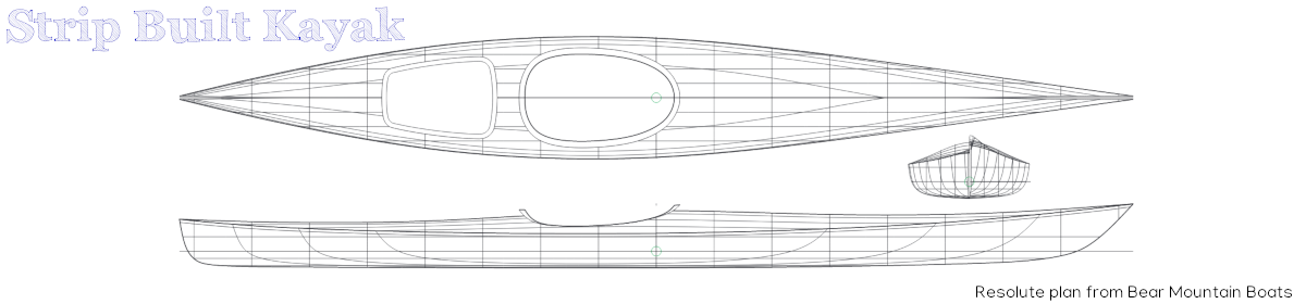
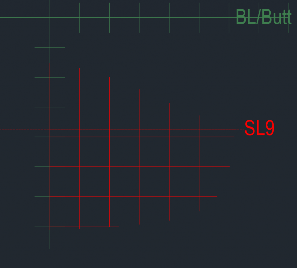
In image 1 you can see the base line (also termed in some texts as a butt line and my center line, or as the text referred to the measurements (distance from water line). What you call them isn’t relevant although naming them to match your lofting table will make it easier to keep track of what you are doing. The first thing I plotted was a line at the sheer line and then I labeled this line for reference. I then started drawing my dots. In this case I started with the deck instead of the hull so it was a much shorter distance from the base line. I simply started at the base line and drew down until I reached the designated measurement.

After drawing each point (line) for the deck I then took the top of each line and moved it down to the sheer line. You’ll get the idea behind doing this in a few more images.
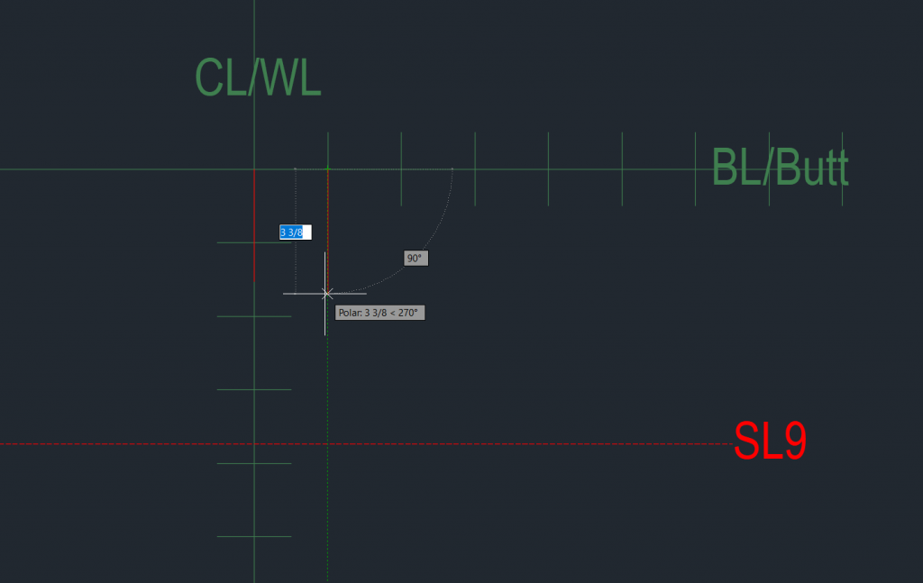
Using the same technique for the hull I drew a line down from the base to the designated point from the lofting table.
And then followed the same process of moving the top of each line down to the sheer line. I then started on the half breadths by coming out from the center line to the designated point.
After completing all the dots for station 9 you can start to already see the shape of the kayak. If I had done this on paper I won’t draw the horizontal and vertical red lines but instead simply put a dot on the paper. For the CAD application, having these lines helped me to visualize what was happening.
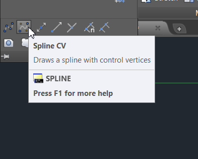
The Spline CV tool in AutoCAD is now my friend. This let’s me specify points that the spline should touch and the software tries to make a smooth line encompassing these points.
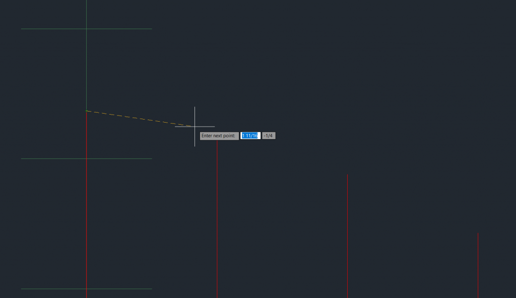
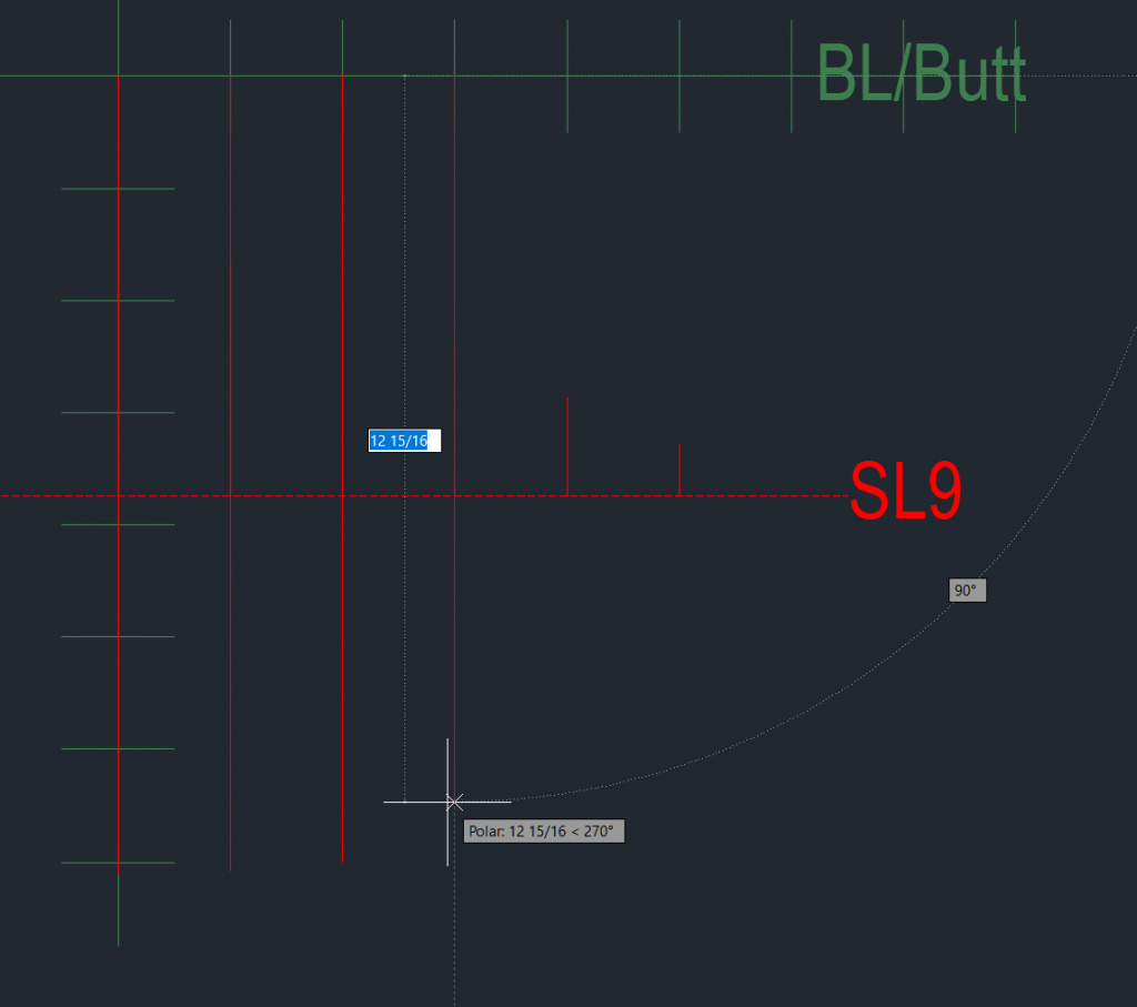
In operation I simply click the first dot at the center line, then in order I click each dot (line end) that makes up the deck and the software creates the curved (fair) line. A fair line is known as a smooth line with no abrupt angles.
As I click the first three points (yellow line) you can see the smooth line (red) that the software is making to try to connect my points.
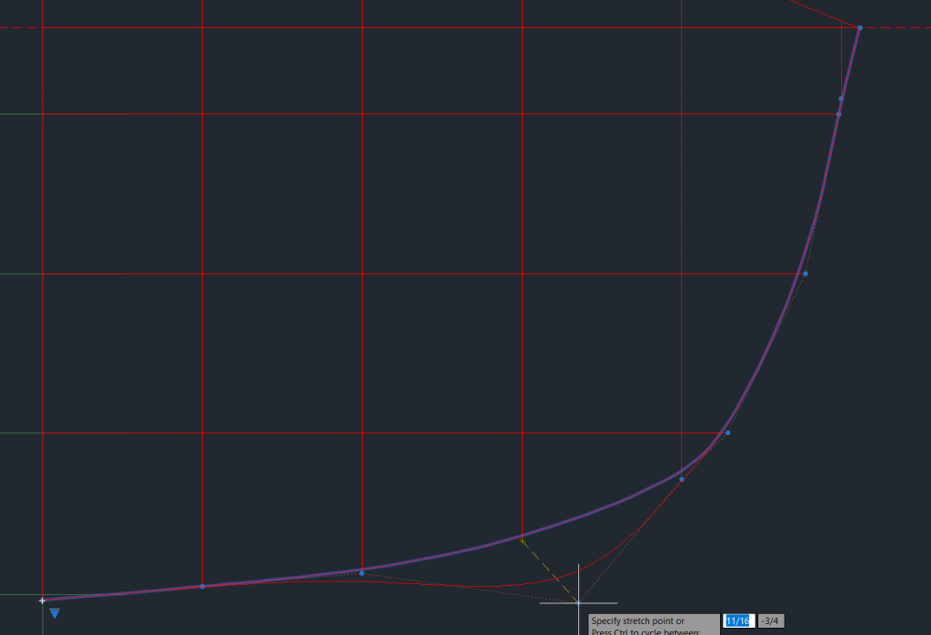
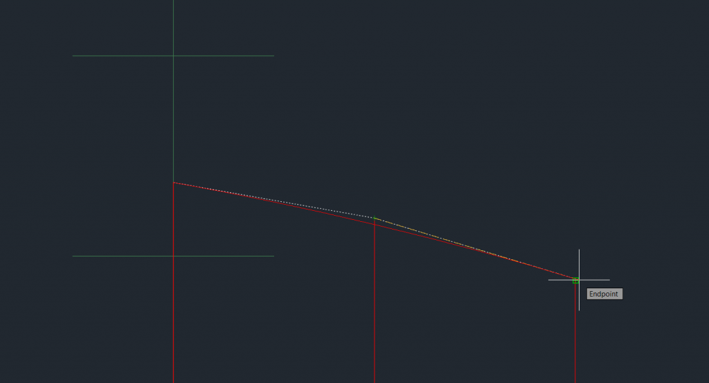
After completing the deck I create a second line for the hull which goes up to the sheer line. Once the line is drawn you can grab any control point (blue dots) and move them around. In this case the purple is the created line and the red is the attempt by the software to incorporate the point that I pulled way out of place. Normally you are looking just for little tweaks to keep the spline as close to your points as possible. Notice just over half way up on the right side the purple line is well inside the blue dot. This is one area I’d tweak to get the spline closer to the dot.
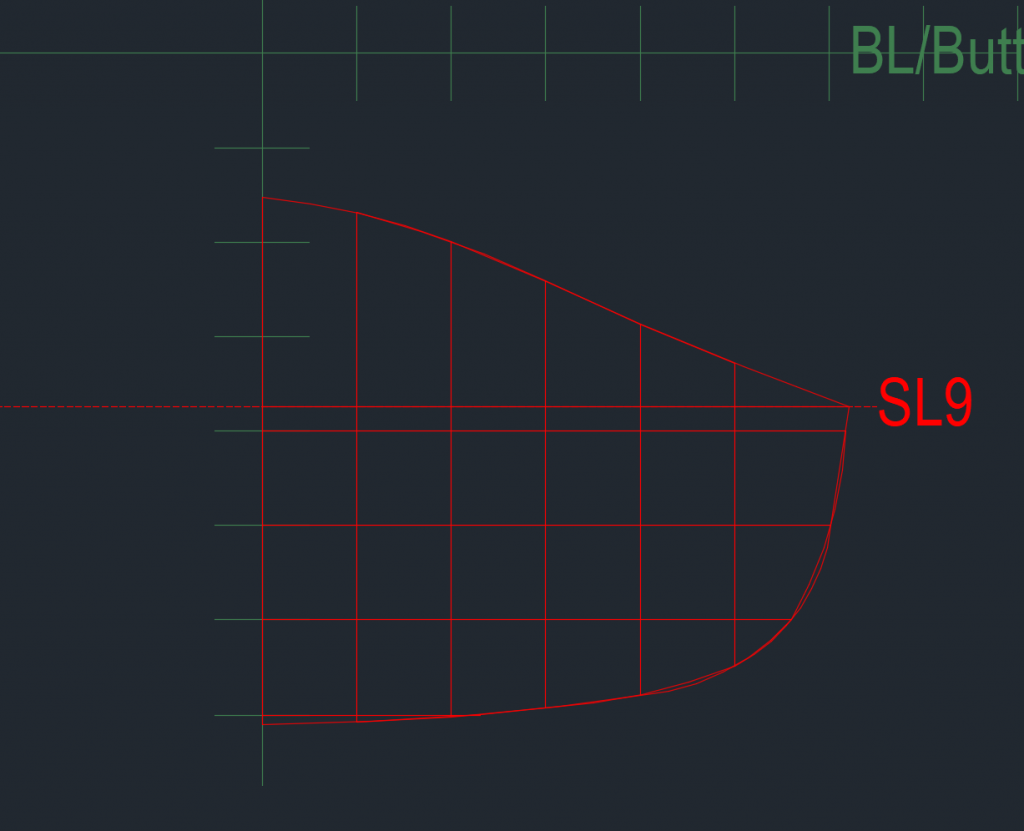
After adjusting the line you are left with a profile of the kayak.
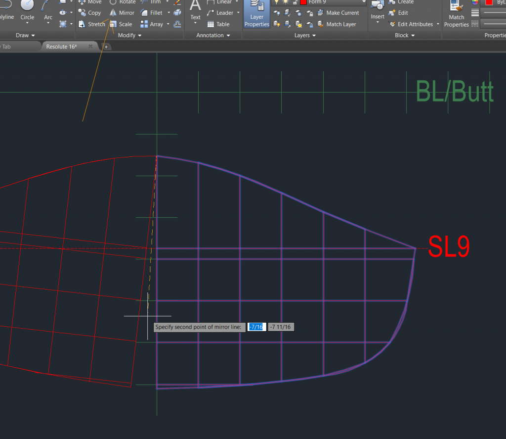
Now the power of the CAD software really comes into play. Instead of having to repeat for the other half of the boat, I simply select the half I drew and use the mirror command to duplicate it.
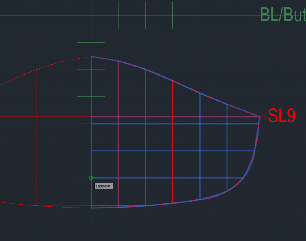
Once you rotate and align the mirrored portion you have a full boat profile at the designated station.
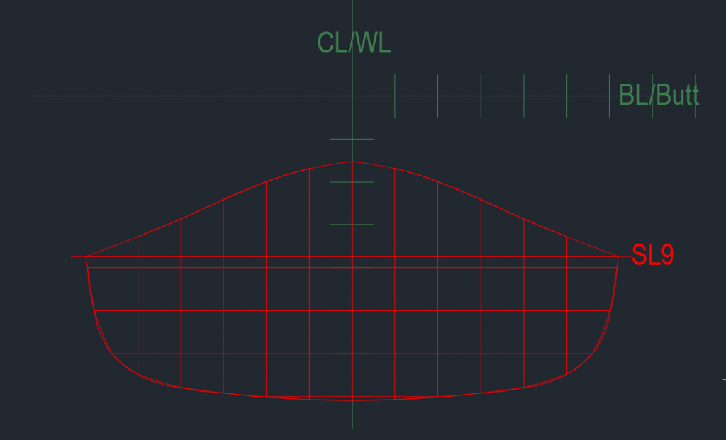
Image 13 shows the completed hull and deck profile for station 9. If it doesn’t look like a slice out of the kayak at this point you probably marked the wrong points or referenced in the wrong direction. Back up and recheck your lofting table conversions and plotted points.
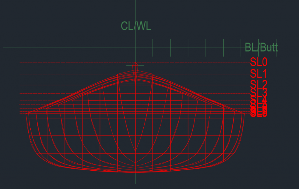
I continued creating the stations, each on their own layer. I then turned all the layers on at once and you can start to really see the full shape of the kayak. Starting at the pointed front, you quickly drop down to a fairly wide and stable body at station 9 (just past the center). If I turned on the remaining layers you’d see the back half of the boat, via these profile slices, too.
After a while I finally looked up the lofting term too as I was curious about it. This whole process is known as lofting the boat. As listed in Wikipedia, lofting is a term to describe the process of making a drawing of a boat from a table of values. The term came about as a result of boat shops being crowded and messy so the drawer(s) would go work in the loft and became known as lofters and the process as lofting.
My next steps are to take the first class and if I’m still ready for a kayak after that, then I’ll bring my CAD file to a CNC shop to turn a 4×8 sheet of MDF into my station forms. One thing not shown on the example above is the 2″ x 4″ rectangle that I measured out on all the forms in the same place (thus higher on some and lower on others. This is where the forms will slide onto my form strongback. I first saw the concept for this in Nick Schade’s videos on You Tube.